Residual-oil discharging system and oil discharging method of emergency oil discharging header pipe

An emergency oil discharge and discharge system technology, applied in the direction of the fuel tank of the power unit, can solve the problems of residual oil discharge, oil tank stringing, etc., to achieve the effect of convenient discharge, simple structure, and avoidance of pump power increase

Active Publication Date: 2015-12-02
XIAN AIRCRAFT DESIGN INST OF AVIATION IND OF CHINA
View PDF9 Cites 10 Cited by
  • Summary
  • Abstract
  • Description
  • Claims
  • Application Information

AI Technical Summary

Problems solved by technology

[0006] The purpose of the present invention is to provide an emergency oil discharge main pipe residual oil discharge system and an oil discharge method to solve the problem of emergency oil discharge main pipe residual oil discharge and the oil tank leakage problem caused by the leakage valve

Method used


Image

  • Residual-oil discharging system and oil discharging method of emergency oil discharging header pipe
  • Residual-oil discharging system and oil discharging method of emergency oil discharging header pipe

Examples


Embodiment Construction

[0027] Reference will now be made in detail to the exemplary embodiments, examples of which are illustrated in the accompanying drawings. When the following description refers to the accompanying drawings, the same numerals in different drawings refer to the same or similar elements unless otherwise indicated.

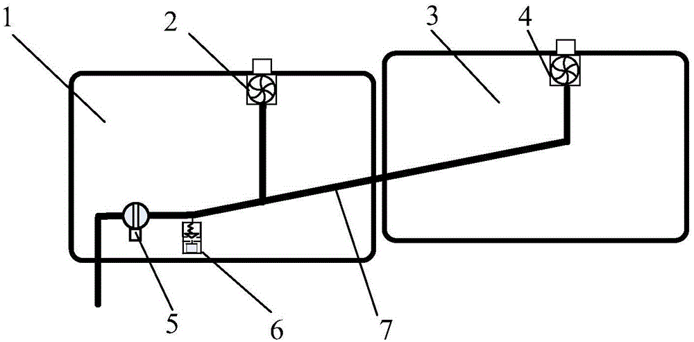
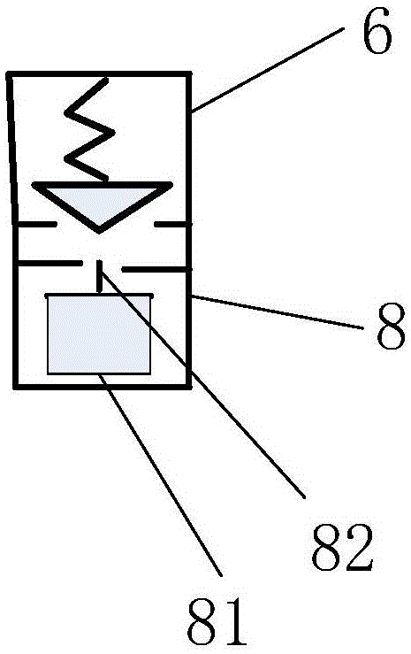
[0028] Such as figure 1 and figure 2 As shown, the emergency oil drain main pipe residual oil discharge system provided by the present invention may include a first fuel tank 3, a second fuel tank 1, an emergency oil drain main pipe 7, a shut-off valve 5, a drain valve 6, a float 8, and the like.

[0029] The emergency fuel drain main pipe 7 is connected between the first fuel tank 3 and the second fuel tank 1 , so that the fuel flows from the first fuel tank 3 to the second fuel tank 1 .

[0030] The first fuel tank 3 is provided with a first emergency oil drain pump 4, and the oil outlet of the first emergency oil drain pump 4 is connected to one end of the emerge...


PUM


Abstract

The invention relates to a design of an emergency oil discharging system of a plane, particularly to a residual-oil discharging system and an oil discharging method of an emergency oil discharging header pipe. The residual-oil discharging system and the oil discharging method are disclosed so as to solve the residual-oil discharging problem of an emergency oil discharging header pipe, and to avoid the mixing of oil in oil tanks caused by a leakage discharge valve. The discharging system comprises the emergency oil discharging pipe header pipe, a leakage discharge valve and a floater, wherein the emergency oil discharging header pipe is arranged between a first oil tank and a second oil tank, are communicated with a first emergency oil discharging pump and a second emergency oil discharging pump respectively, and are connected with a cut-off valve; the leakage discharge valve is arranged at the lowest position of the emergency oil discharging header pipe in the second oil tank, and is positioned at the upstream of the cut-off valve; the floater is arranged at an outlet at the bottom of the leakage discharge valve, and is used for sealing and blocking the leakage discharge valve. According to the invention, the leakage discharge device is simple in structure; by the use of the leakage discharge device, the residual oil of the oil discharging header pipe of the plane can be conveniently discharged, so that the adverse influences, such as pump power increase, efficiency decrease, weight increase and the like, caused by reduction of forward leakage of an emergency oil discharging pump, are avoided, and the adverse influence of mixing of oil from different oil tanks and plane preparation time prolongation due to employment of a common leakage discharge valve is avoided.

Description

technical field [0001] The invention relates to the design of an aircraft emergency oil discharge system, in particular to an emergency oil discharge main pipe residual oil discharge system and an oil discharge method. Background technique [0002] Aircraft emergency oil drain is used to discharge the fuel in the aircraft fuel tank in an emergency to reduce the weight of the aircraft and facilitate the landing of the aircraft. [0003] For large aircraft with emergency fuel drain requirements, usually one or two booster pumps are used as emergency fuel drain pumps for each group of fuel tanks, and the emergency fuel drain main pipe is connected to the booster pumps of each group of fuel tanks. The emergency oil drain main pipe is longer and has more excess oil. In order to make the remaining oil available, a drain valve needs to be added on the pipeline; when the inlet pressure is higher than the specified pressure, the drain valve will be closed, and when the inlet pressur...

Claims


Application Information

Patent Timeline
Patent Type & Authority Applications(China)
IPC IPC(8): B64D37/20
Inventor 马少璞林厚焰刘苏彦余国际
Owner XIAN AIRCRAFT DESIGN INST OF AVIATION IND OF CHINA
Why Eureka
Try Eureka