Automatic slurry conveying device used for high-altitude in building room and using method thereof

A technology of automatic conveying device and slurry, applied in the directions of liquid distribution, conveying or transfer device, distribution device, transportation and packaging, etc., can solve the problem of inconvenience of slurry

Inactive Publication Date: 2015-12-02
广东景龙嘉园装饰工程股份有限公司
View PDF7 Cites 1 Cited by
  • Summary
  • Abstract
  • Description
  • Claims
  • Application Information

AI Technical Summary

Problems solved by technology

[0007] The purpose of the present invention is to provide a slurry automatic conveying device and its use method to solve the inconvenience of construction personnel taking slurry when working in the air

Method used


Image

  • Automatic slurry conveying device used for high-altitude in building room and using method thereof
  • Automatic slurry conveying device used for high-altitude in building room and using method thereof
  • Automatic slurry conveying device used for high-altitude in building room and using method thereof

Examples


Embodiment 1

[0083] This embodiment provides an automatic slurry conveying device for high-place construction in a building, the automatic slurry conveying device includes a storage tank, a power mechanism, and a discharge mechanism, and the storage tank and the discharge mechanism They are connected by connecting pipes, and the power mechanism is used to provide the power for conveying slurry to the discharging mechanism, and the discharging mechanism is provided with a discharging control switch for controlling the conveying of slurry.

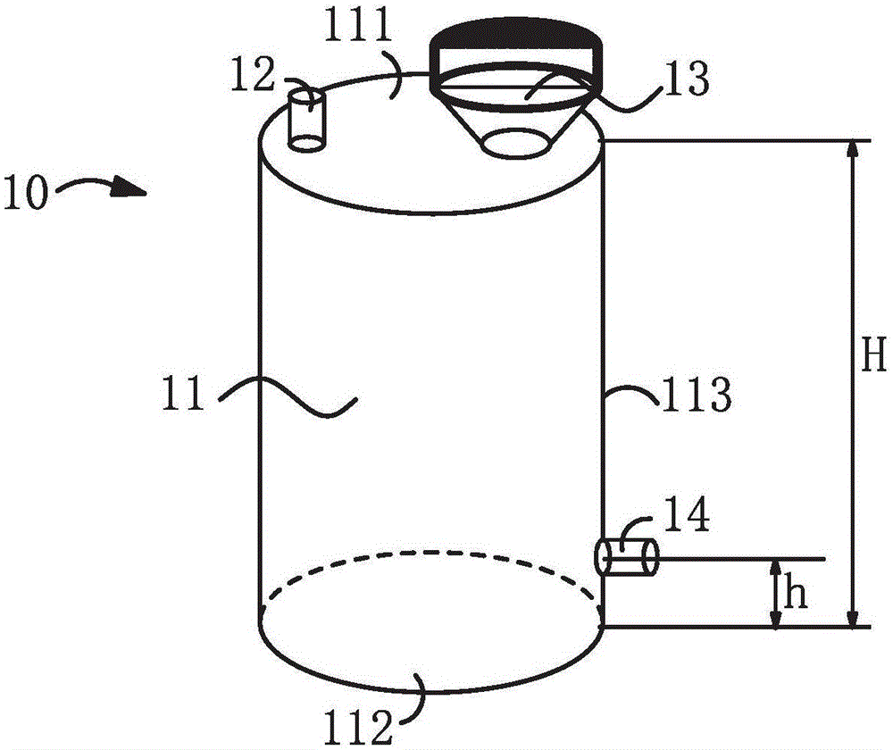
[0084] Wherein, the storage tank includes a tank body for holding the slurry, the top of the tank body is provided with an air inlet and a feeding part, the side wall of the tank body is provided with a discharge port, and the discharge mechanism includes A discharge part and a holding part, the front end of the discharge part is a discharge port, the rear end is connected to the front end of the holding part, and the rear end of the holding part is conne...

Embodiment 2

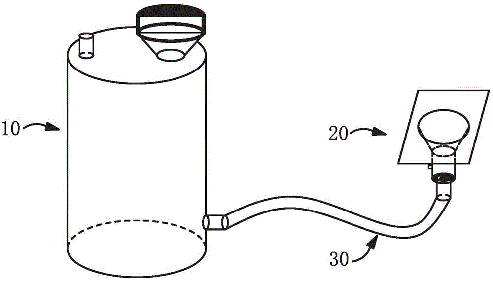
[0086] This embodiment provides an automatic slurry conveying device for construction at a high place in a building, such as the ceiling of a home or an office or a construction operation at a high place on a wall, such as figure 1 As shown, the conveying device includes a storage tank 10 , a power mechanism and a discharge mechanism 20 , and a connecting pipe 30 for connecting the storage tank 10 and the discharge mechanism 20 . Among them, the storage tank and the discharge mechanism are different independent structures. During construction, the two ends of the connecting pipe can be inserted into the storage tank and the discharge mechanism respectively to connect the two. Disconnect from the storage tank and the discharge mechanism respectively. It can be seen that the automatic slurry conveying device of the present invention is flexible in disassembly and assembly, and can be conveniently used in different construction occasions. In addition, the connecting pipe in this...

Embodiment 3

[0096] The difference between this embodiment and the second embodiment lies in the improvement of the discharge panel. Such as Image 6 As shown, in this embodiment, a side wall 26 is formed extending upward from the edge of the discharge panel 25 , and the discharge panel 25 and the side wall 26 jointly enclose to form an accommodating tank 40 capable of containing slurry.

[0097] Different slurries have different viscosities and corresponding fluidity. When the slurry with high viscosity and low fluidity is output, it first accumulates in the center of the discharge panel, and then slowly accumulates around due to the increase of the accumulation amount; while the slurry with low viscosity and high fluidity is discharged When it is difficult to accumulate and form, it is easier to flow around. If only the discharge panel is used to hold this type of slurry, the slurry is likely to overflow from the panel, but the improvement of this embodiment can just overcome this defe...


PUM


Abstract

The invention provides an automatic slurry conveying device used for high-altitude construction in a building room. The automatic slurry conveying device comprises a storage tank, a power mechanism and an electric discharge mechanism, wherein the storage tank and the discharge mechanism are connected by virtue of a connecting tube; the power mechanism is used for providing slurry conveying power to the discharge mechanism; and a discharge control switch for controlling slurry conveying is arranged on the discharge mechanism. The invention further provides a using method of the automatic slurry conveying device. The using method comprises the following steps: firstly, adding the slurry into the storage tank; then, carrying the automatic slurry conveying device to a position below a position, which needs high-altitude construction, in the building room; and finally, moving out the discharge mechanism to a working position, and starting the discharge control switch for automatically outputting the slurry to a wall at the working position through the discharge mechanism. With the adoption of the device disclosed by the invention, the slurry conveying operation is relatively convenient and quick; meanwhile, part of labor power can be saved and the working efficiency can be improved; besides, the automatic slurry conveying device further also realize supplying materials to multiple persons and supplying materials remotely, and has remarkable beneficial effects.

Description

technical field [0001] The invention relates to the technical field of slurry transportation for building construction, in particular to an automatic slurry delivery device for construction at high places inside a building and a method for using the same. Background technique [0002] In the construction process of building decoration, mortar, dry powder coating or putty are often used. Slurry is generally made by mixing solid materials and water in a certain proportion, and has certain fluidity or plasticity. It needs to be placed in a slurry bucket when mixing, and an appropriate amount should be taken out of the slurry bucket and placed on a flat plate when used. For painting walls etc. Construction personnel usually need to place slurry buckets according to the construction location, so as to facilitate the use of slurry for construction. [0003] However, in the construction process, construction workers will inevitably construct the ceiling or the higher position of ...

Claims


Application Information

Patent Timeline
IPC IPC(8): B67D7/02
Inventor 陈贤耿
Owner 广东景龙嘉园装饰工程股份有限公司
Why Eureka
Try Eureka