Door Bottom Gap Sealing Device and Its Application in Fire Doors and Refuge Cells
A sealing device and gap technology, applied in the field of door bottom gap sealing devices, can solve the problems of troublesome installation, poor plasticity and flame retardancy, and narrow application range, and achieve the effects of convenient installation, good fire resistance and wide applicability
- Summary
- Abstract
- Description
- Claims
- Application Information
AI Technical Summary
Problems solved by technology
Method used
Image
Examples
Embodiment 1
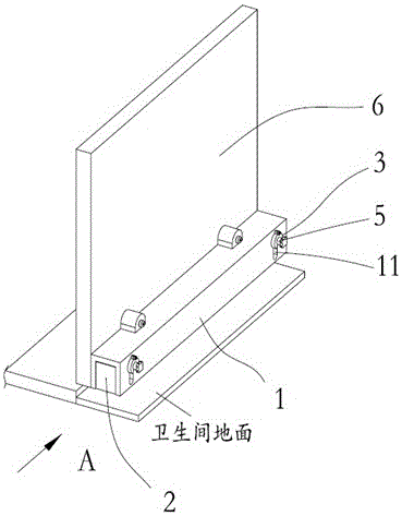
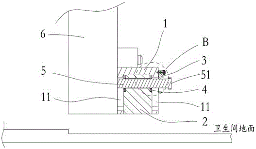
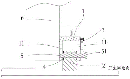
[0040] like figure 1 As shown, a door bottom gap sealing device, which is located at the bottom of the door body 6, includes a U-shaped guide sleeve 1, a foam glass block 2, a fixing piece, a reinforcement block 4 and an opening and closing bolt 5, and the fixing piece is a notched elastic Ring rubber sleeve 3.
[0041] The width of the U-shaped guide sleeve 1 and the foam glass block 2 is consistent with the width of the door body 6. The U-shaped open end of the U-shaped guide sleeve 1 is downward and fixed on the bottom of the door body 6. The two ends of the U-shaped guide sleeve 1 both sides All are provided with elongated chute 11.
[0042] like Figure 2~3 As shown, the height of the foam glass block 2 is greater than the height of the gap at the bottom of the door, and it is embedded in the opening end of the U-shaped guide sleeve 1. The two ends of the foam glass block 2 are provided with pin holes 21, and the elastic ring rubber sleeve 3 is located in the U-shaped g...
Embodiment 2
[0054] The door bottom gap sealing device of this embodiment is basically the same as that of Embodiment 1, the difference lies in that the fixing parts are two arc-shaped latches 7 .
[0055] like Image 6 As shown, the arc lock 7 includes an arc lock arm 71, a rotating shaft 72 and a magnet-absorbing piece 73. The arc-shaped lock arm 71 is fixed on the U-shaped guide sleeve 1 through the rotating shaft 72, and the magnet-absorbing piece 73 is fixed on the arc-shaped The bottom of the locking arm 71 is in contact with the outer edge, and a pressing portion 74 is provided above the arc-shaped locking arm 71 .
[0056] The installation process of this embodiment is as follows:
[0057] 1. Install and fix the reinforcing block 4 above the foam glass block 2, so that the outer pin hole 41 of the reinforcing block 4 is coaxial with the pin hole 21 of the foam glass block 2.
[0058] 2. Install the two arc locks 7 above the elongated chute 11 of the U-shaped guide sleeve 1 throug...
PUM
 Abstract
Description
Claims
Application Information
 - R&D
- Intellectual Property
- Life Sciences
- Materials
- Tech Scout
- Unparalleled Data Quality
- Higher Quality Content
- 60% Fewer Hallucinations
Browse by: Latest US Patents, China's latest patents, Technical Efficacy Thesaurus, Application Domain, Technology Topic, Popular Technical Reports.
© 2025 PatSnap. All rights reserved.Legal|Privacy policy|Modern Slavery Act Transparency Statement|Sitemap|About US| Contact US: help@patsnap.com


