Multi-cylinder rotary compressor
A technology for a rotary compressor and a compression mechanism, applied in the field of compressors, can solve problems such as oil shortage, crankshaft and bearing wear failures of the rotary compressor, and achieve the effects of reducing sliding wear and reducing compressor vibration
- Summary
- Abstract
- Description
- Claims
- Application Information
AI Technical Summary
Problems solved by technology
Method used
Image
Examples
Embodiment 1
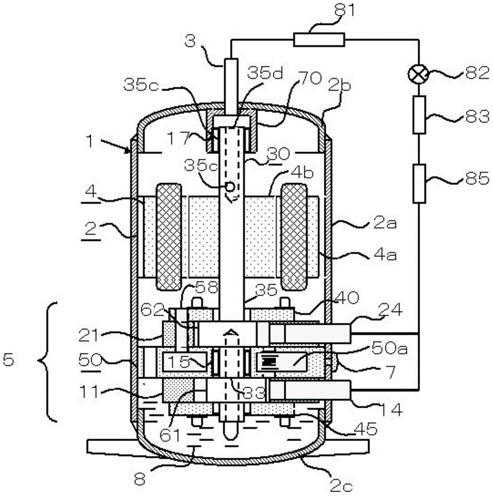
[0067] figure 1 In the illustrated multi-cylinder rotary compressor 1 , the outer periphery of the stator 4 a constituting the motor 4 and the outer periphery of the intermediate partition plate 50 provided at the center of the compression mechanism unit 5 are fixed to the inner diameter of the hermetic casing 2 . The casing 2 is composed of three parts: a cylindrical casing 2a, an upper end plate 2b and a lower end plate 2c welded to the upper and lower ends thereof. Usually, the cylindrical shell 2a and the stator 4a are fixed by shrink fit, and the middle partition plate 50 and the shell 2 are fixed by spot welding at 3 to 5 points. In addition, oil 8 is stored at the bottom of the housing 2 .
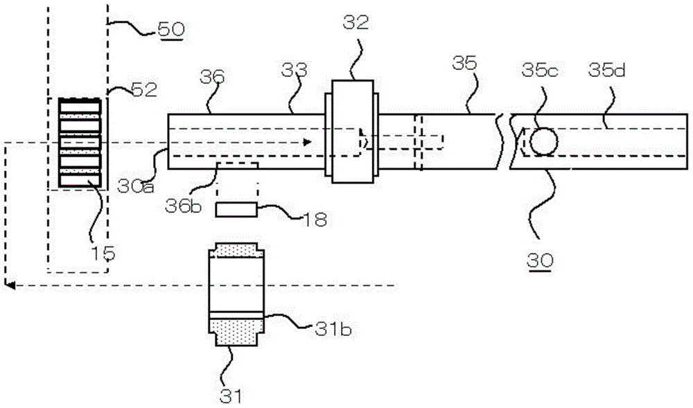
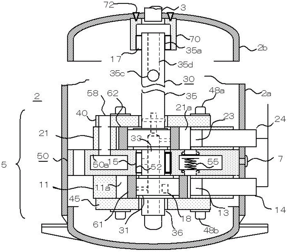
[0068] The compression mechanism part 5 is composed of the first cylinder 11 and the second cylinder 21, the first seal plate 45 and the second seal plate 40 connected to these opening surfaces, and the seal between the first cylinder 11 and the second cylinder 21 and connected to ...
Embodiment 2
[0090] The rotary compressor has a small internal volume of the casing relative to the displacement. Due to the high-speed rotation of the rotor 4b, a large amount of gas discharged from the two compression chambers agitates the oil 8 of the cylindrical case 2a, together with the discharged gas, and is ejected to the upper space of the motor through the motor 4. The problem is that due to high-speed operation, the oil cannot return to the lower part of the cylindrical case 2a, and a large amount of oil may be discharged from the exhaust pipe into the refrigeration cycle system.
[0091] Embodiment 2 is a means of improving this problem, and the effect of the main shaft outer peripheral hole 35c adopted in Embodiment 1 can be greatly improved. exist Figure 4 Among them, the outer periphery of the cylindrical plate 66 fixed to the upper end of the rotor 4b by the bushing screw 67 has several outer peripheral holes 66a. Due to the centrifugal separation effect of the high-spee...
Embodiment 3
[0095] Figure 6 The first ball bearing 25 is provided in the middle partition plate 50, and the second ball bearing 27 is provided in the end plate bearing 70. As a substitute for the needle bearing, a ball bearing can be used. in addition, Figure 6 The arrangement of the first slide piece 63 and the second slide piece 64 is shown.
[0096] Compared with needle roller bearings and ball bearings, the outer diameter is larger and the thickness is smaller. Therefore, it is difficult to use the outer diameter of the ball bearing as the inner diameter of the intermediate bearing 52 . Because the inner diameter of the intermediate bearing 52 is very large to the center of the compression chamber, the sliding surface of the piston is limited, and the amount of eccentricity of the piston becomes smaller. In order to solve this problem, Figure 6 It shows how the outer diameter portion of the first ball bearing 25 can be housed in the upper and lower middle partition plate 50 whi...
PUM
 Abstract
Description
Claims
Application Information
 - R&D
- Intellectual Property
- Life Sciences
- Materials
- Tech Scout
- Unparalleled Data Quality
- Higher Quality Content
- 60% Fewer Hallucinations
Browse by: Latest US Patents, China's latest patents, Technical Efficacy Thesaurus, Application Domain, Technology Topic, Popular Technical Reports.
© 2025 PatSnap. All rights reserved.Legal|Privacy policy|Modern Slavery Act Transparency Statement|Sitemap|About US| Contact US: help@patsnap.com


