Back cover displacement type torque amplifier

A torque amplifier and displacement technology, applied in the direction of fluid pressure actuating device, servo motor, servo motor assembly, etc., can solve the problems of single connection method, limited application scope, and inability to install flexibly.

Inactive Publication Date: 2015-12-02
ZHENJIANG HYDRAULICS
View PDF6 Cites 0 Cited by
  • Summary
  • Abstract
  • Description
  • Claims
  • Application Information

AI Technical Summary

Problems solved by technology

[0004] As far as the applicant understands, when the torque amplifier of the prior art is connected to the supporting host, it mainly relies on the two port holes on its back cover, but because the positions of the two por

Method used


Image

  • Back cover displacement type torque amplifier
  • Back cover displacement type torque amplifier
  • Back cover displacement type torque amplifier

Examples


Embodiment 1

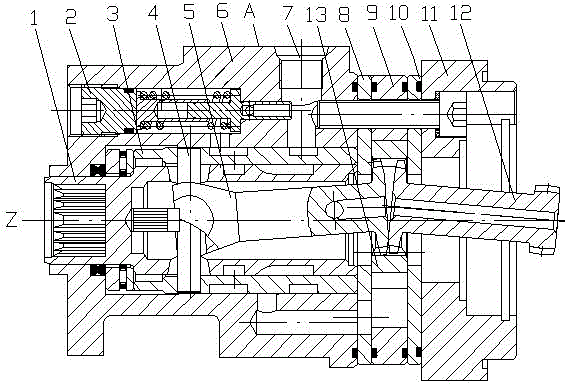
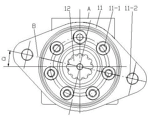
[0015] The rear cover displacement type torque amplifier of the present embodiment is as figure 1 with figure 2 As shown, the base plane A of the housing 6 has an oil inlet and an oil return port 7, and the housing 6 is fixed along the main axis Z direction with the stator 9 and the rear cover 11 clamped by the front partition 9 and the rear partition 10 connect. A valve core sleeve 3 supporting the valve core 1 is housed in the housing 6, and a rotor 13 forming a cycloidal pin-wheel pair is housed in the stator 9. The inner hole of the rotor 13 is meshed with the opposite ends of the input linkage shaft 5 and the output linkage shaft 12 through an inner spline. The other end of the input linkage shaft 5 is connected to the valve core sleeve 3 through the dial pin 4 , and the other end of the output linkage shaft 12 passes through the rear cover 11 . Figure 2 is a safety overflow valve installed on one side of the housing.

[0016] The rear cover 11 has seven perforations...

Embodiment 2

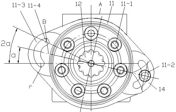
[0018] The basic structure of the rear cover displacement type torque amplifier of this embodiment is the same as that of Embodiment 1, the differences are as follows image 3 , 4 , 5, the back cover 11 is respectively formed with a base circle depression 11-3 corresponding to the two installation holes, and the base circle depression 11-3 is formed with an arc groove 11-4 adapted to the position of the installation hole, and the arc groove 11- The center line of symmetry of 4 passes through the center of one of the through holes 11-1 and forms an included angle a=(360°÷7) / 2 with the radial direction of the main axis parallel to the reference plane. Both ends of the arc groove 11-4 are transitional semicircles r, and the center angle of the center of the transitional semicircle at both ends corresponding to the main axis is 2a. The base circle recess 11-3 is embedded with an insert 14 whose outer contour matches the base circle and has a mounting hole 11-2.

[0019] In this ...


PUM


Abstract

The invention relates to a back cover displacement type torque amplifier, which belongs to the hydraulic technical field, which comprises a shell body with a datum plane provided with an oil inlet and an oil return port, wherein the shell body is fixedly connected to a stator clamped between front and back spacer discs and a back cover along the direction a main axis; a valve core sleeve used for supporting a valve core is mounted inside the shell body; a rotor that is used together with the stator to form a cycloid pin gear pair is mounted inside the stator; an inner hole of the rotor is simultaneously engaged with opposite ends of an input linkage shaft and an output linkage shaft through an internal spline; the other end of the input linkage shaft is connected to the valve core sleeve through a poke pin and the other end of the output linkage shaft penetrates out of the back cover; and the back cover is provided with seven through holes evenly distributed along main axis circumference and two opposite mounting holes at the outer side of the circumference on which the through holes are located. According to the invention, the torque amplifier has enough connection strength; the torque amplifier is matched with the number of teeth of the cycloid pin gear pair; and the mounting holes have more than seven directional assembly positions, thus the torque amplifier can be suitable for various main machines.

Description

technical field [0001] The invention relates to a torque amplifier, in particular to a rear cover displacement type torque amplifier, which belongs to the technical field of hydraulic pressure. Background technique [0002] The cycloid rotary valve torque amplifier can convert the driver's small steering torque into a hydraulic component with large torque output. The operation is labor-saving, flexible, stable and compact. It is mainly used for rice transplanters, excavators and large manual gate valves, etc. Mechanical equipment requiring greater torque control. [0003] Its basic components (refer to the Chinese patent document with application number 201520114680.X and titled "An Integrated Torque Amplifier") are a control valve composed of a spool sleeve and a metering amplifying meshing pair composed of a cycloidal pinwheel. The function of the control valve is hydraulic reversing, that is, with the left and right rotation of the steering wheel and the speed of the rot...

Claims


Application Information

Patent Timeline
IPC IPC(8): F15B11/032F15B13/02
Inventor 焦文瑞潘骏秦志文
Owner ZHENJIANG HYDRAULICS
Why Eureka
Try Eureka