
Water sample acquisition device and use method thereof

A collection device and water sample technology, applied in the direction of sampling devices, etc., can solve problems such as complex structure, high production cost, and impact on measurement accuracy, and achieve the effects of accurate collection position, good underwater stability, and exquisite structure

Active Publication Date: 2015-12-02
JIANGSU ELECTRIC POWER COMPANY YANGZHOU POWER +1
View PDF4 Cites 29 Cited by
  • Summary
  • Abstract
  • Description
  • Claims
  • Application Information

AI Technical Summary

Problems solved by technology

Generally speaking, the classification can be divided into two categories: one is through circuit control, such as a Chinese patent application titled "A Water Sample Collector" published by the National Bureau on April 3, 2013, and the application number is "20121049608.4". Invention patent; it has good operation convenience and accurate measurement position; however, it also has problems such as complex structure, high production cost and poor underwater stability; A Chinese invention patent titled "Deep Water Sample Collector" with application number "2011103838412.2" announced in Japan has a simple structure and is easy to use. The piston will be opened or closed under the action of a spring. However, due to the The water pressure will change linearly with the depth. Therefore, the piston in this case will open and close slowly and gradually during use, so that the water sample is easily mixed with shallow water, which has a certain impact on the measurement accuracy.

Method used


Image

  • Water sample acquisition device and use method thereof
  • Water sample acquisition device and use method thereof
  • Water sample acquisition device and use method thereof

Examples


Embodiment Construction

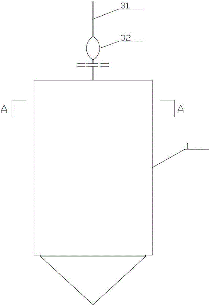
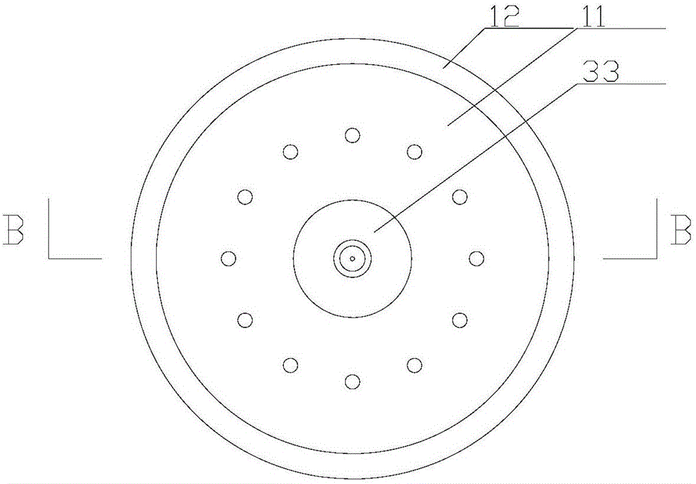
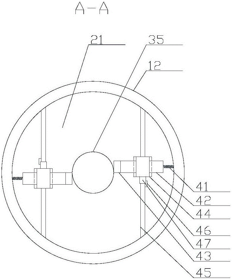
[0038] The invention as Figure 1-7 As shown, it includes a shell assembly 1, a lining assembly 2, a drag assembly 3 and a pair of opening and closing assemblies 4;

[0039] The shell assembly 1 includes a top plate 11, a side cylinder 12 and a counterweight 13. The side cylinder 12 is in the shape of a straight cylinder. The top plate 11 is detachably connected to the top of the side cylinder 12, and a threaded hole is opened in the center of the top plate 11. , the counterweight 13 is detachably connected to the bottom of the side cylinder 12, and the lower part of the side cylinder 12 is also provided with a number of water inlet holes 120 with a straight height, and the water inlet holes 120 are located on the counterweight 13 above the top surface of the

[0040] The lining assembly 2 includes a straight barrel-shaped water storage bucket 21 and a hollow floating plate 22. The opening of the water storage bucket 21 faces downward, and its outer wall closely fits the inne...


PUM


Abstract

The invention discloses a water sample acquisition device and a use method thereof and relates to the field of hydrographic survey equipment. The water sample acquisition device comprises a housing assembly, an inner liner assembly, a drawing assembly and a pair of on-off assemblies. The use method comprises manual operation: initialization, dropping, lifting, standing, recovery and water collection, and mechanical operation: initialization, fast dropping, driving stopping, closing state keeping, rope reeling and water collection. In use, a water sample at designated depth flows to a position below a floating plate from a water inlet hole from bottom to top, and after the water sample is completely sucked, the floating plate, a water storage tank and a balancing weight form an individual and sealed water storage space so that in water sample acquisition device upstream movement, shallow water is not mixed. The water sample acquisition device has an accurate acquisition position and avoids mixing with shallow water. The water sample acquisition device with a pure mechanical structure has the characteristics of exquisite structure, use convenience and good underwater stability. The water sample acquisition device has the characteristics of fast water sample suction rate, high work efficiency and use convenience.

Description

technical field [0001] The invention relates to the field of hydrological measuring equipment, in particular to the improvement of the water sample collecting device. Background technique [0002] At present, when testing the water quality of rivers, lakes and other water bodies in water level survey work, it is required to sample and analyze water bodies at different locations and at different depths. Most of the existing water samples are taken on the shore. There are also samples taken in ships, which can more truly reflect the actual conditions of the water body. Generally speaking, the classification can be divided into two categories: one is through circuit control, such as a Chinese patent application titled "A Water Sample Collector" published by the National Bureau on April 3, 2013, and the application number is "20121049608.4". Invention patent; it has good operation convenience and accurate measurement position; however, it also has problems such as complex struc...

Claims


Application Information

Patent Timeline
IPC IPC(8): G01N1/10
Inventor 李培培黄俊黄晔暄李晖映徐云清王木楠
Owner JIANGSU ELECTRIC POWER COMPANY YANGZHOU POWER
Learn More