
Method and device for shearing test on interface between steel bridge deck and pavement layer

A shear test and pavement technology, applied in the direction of measuring devices, mechanical devices, instruments, etc., can solve the problems of test influence, test deviation, and inconformity with the actual state of the pavement, etc., to achieve convenient operation and simple structure Effect

Inactive Publication Date: 2015-12-02
CHANGSHA UNIVERSITY OF SCIENCE AND TECHNOLOGY +1
View PDF6 Cites 14 Cited by
  • Summary
  • Abstract
  • Description
  • Claims
  • Application Information

AI Technical Summary

Problems solved by technology

[0004] The prior art discloses a jig and method for testing interlayer shear fatigue specimens of pavement, only considering the horizontal friction force of the vehicle on the road surface, ignoring the vertical pressure of the vehicle, and both forces can generate The shear stress obviously does not conform to the actual state of the pavement; the operation of the oblique shear test is simple, but the disadvantage is that stress concentration occurs when the specimen and the test mold are in contact, which has a certain impact on the test
Therefore, the current existing test devices cannot accurately measure the shear characteristics of the steel bridge deck pavement, and there will be test deviations

Method used


Image

  • Method and device for shearing test on interface between steel bridge deck and pavement layer
  • Method and device for shearing test on interface between steel bridge deck and pavement layer
  • Method and device for shearing test on interface between steel bridge deck and pavement layer

Examples


Embodiment

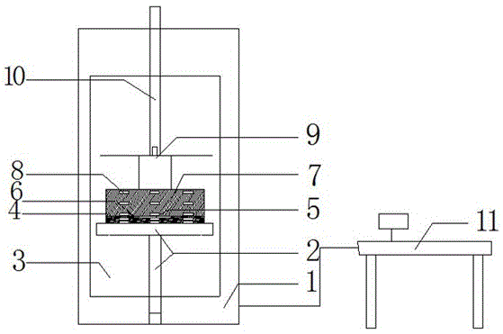
[0055] A kind of method for steel bridge deck and pavement interface shear test, comprises the following steps:

[0056] 1. Preparation of the test piece: Forming the steel plate, processing the 16mm thick steel plate into a 300mm×50mm rectangular steel plate on the machine tool. For the surface treatment of the steel plate, use a sandblasting machine to polish the steel plate to a roughness that meets the requirements, and manually polish the parts that cannot be treated by the sandblasting machine at the corners with a hand grinding wheel. Lay the adhesive layer, wipe the steel plate after polishing, and scrape the epoxy waterproof adhesive layer material. The bonding layer of the specimen was laid in two stages, and at the same time as the waterproof bonding material was scraped for the second time, single-grain gravel was spread. No bonding layer is laid in the middle third of the distance of the specimen, forming an empty layer, that is, a pure bend section. After the a...


PUM


Abstract

The invention discloses a method and device for a shearing test on the interface between the steel bridge deck and the pavement layer, and relates to the technical field of highway steel bridge deck pavement. The technical scheme includes the following key points: the test method includes test piece manufacture, heat preservation of the test piece, shearing test, and deduction of the relationship between the shearing stress and shearing strain of the interfacial layer according to the linear strain measured using a strain gage on the test piece. The invention also discloses a device for realizing the test method, and the device includes a material testing machine and a console; an environmental chamber is arranged on the inner side of the material testing machine; a loading rod, a three-point loading mold and a support platform are arranged on the inner side of the environmental chamber; in the working state, the test piece is placed between the three-point loading mold and the support platform. The test method and device, provided by the invention, are compatible with various experimental conditions; in addition, the device for the shearing test on the interface between the steel bridge deck and the pavement layer is simple in structure; the testing method is easy to operate, can accurately measure the shearing strain under different shearing stress conditions, and provides basis for the studying on shearing characteristics of the interface in a nonlinear bonding and slipping state.

Description

technical field [0001] The invention relates to the technical field of deck pavement of highway steel structure bridges, in particular to a shear test method and device for the interface between a steel bridge deck and a pavement layer. Background technique [0002] With the rapid development of my country's economy, the construction of highways and bridges has ushered in a new peak of development. There are more and more constructions of long-span steel box girder bridges. Steel deck pavement is an important part of the bridge structure. Under the combination of factors such as vehicle loads and environmental temperature changes, the interface damage between the steel bridge deck and the pavement layer is one of the main defects of the steel deck pavement, which is specifically manifested as pushing Permanent deformation and delamination, cracks and other diseases. The mechanical reasons for the failure of the steel bridge deck pavement are mainly: 1. The existence of the...

Claims


Application Information

Patent Timeline
IPC IPC(8): G01N19/04
Inventor 赵锋军鲁国烽陈修和张玉斌
Owner CHANGSHA UNIVERSITY OF SCIENCE AND TECHNOLOGY
Learn More