
Digital PET energy parameterization calibration method and system

A calibration method and calibration system technology, applied in the direction of using radiation for material analysis, etc., can solve the problems of operator physical damage, time-consuming, energy value deviation, etc., to improve work safety, high efficiency, and accuracy guarantee. Effect

Inactive Publication Date: 2015-12-02
RAYSOLUTION DIGITAL MEDICAL IMAGING CO LTD
View PDF7 Cites 11 Cited by
  • Summary
  • Abstract
  • Description
  • Claims
  • Application Information

AI Technical Summary

Problems solved by technology

Therefore, when the detector is determined, the energy calculations between the various detection modules are independent of each other, but because the system uses multiple crystals and photoelectric conversion devices, and there will be differences between circuits, the same method is used to calculate the energy received by the crystal. After the energy calculation of the γ photons with the same energy, the energy value corresponding to the count peak value detected by each crystal has a certain deviation from the energy value corresponding to the theoretical count peak value, and the calculated energy of each channel needs to be normalized Correction
[0005] In order to ensure the accuracy of the PET system, the energy calibration of the PET system needs to be performed regularly when the PET system is in normal use. In addition, if one or more detection modules of the PET system fail and are replaced, the energy calibration of the PET system is also required. In the existing PET energy correction technology, it is often necessary to use a radiation source. The steps of energy correction are cumbersome, troublesome, time-consuming, and long-term exposure to the radiation source environment may cause certain damage to the operator’s body.

Method used


Image

  • Digital PET energy parameterization calibration method and system
  • Digital PET energy parameterization calibration method and system

Examples


Embodiment Construction

[0029] The present invention will be further described below in conjunction with the embodiments shown in the accompanying drawings.

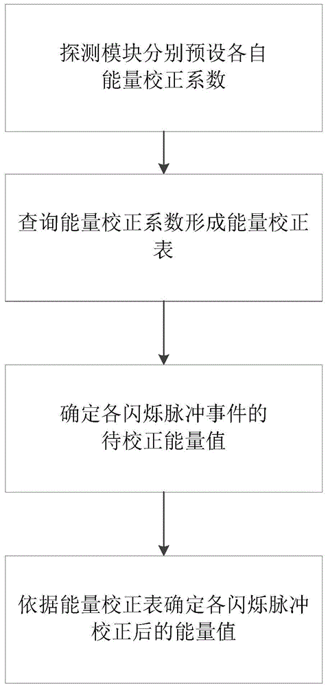
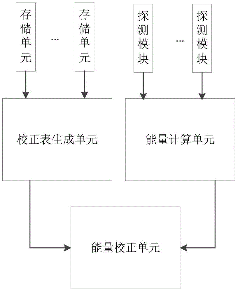
[0030] The invention discloses a digital PET energy parametric correction method and system, which is applied to the digital PET. The digital PET includes a plurality of detection modules, and each detection module includes crystal strips coupled one by one and a photomultiplier. In addition, Each detection module also presets a corresponding energy correction coefficient. When working, when each detection module is powered on, the upper computer reads the energy correction coefficient of each detection module and forms an energy correction table corresponding to the detection module of this work. After the scintillation pulse events of each detection module are collected, they are sent to In the host computer, the host computer calculates the energy to be corrected for each scintillation pulse event, and corrects the energy of the scintillatio...


PUM


Abstract

The invention discloses a digital PET energy parameterization calibration method. According to the digital PET energy parameterization calibration method, each detector module is provided with corresponding energy calibration coefficients via presetting; each detector module comprises one-to-one coupled crystal strips and silicon photomultipliers. The digital PET energy parameterization calibration method comprises following steps: (1) an upper computer is used for inquiring the preset energy calibration coefficients in each detector module so as to obtain an energy calibration chart; (2) the upper computer is used for acquiring energy values for calibration of each scintillation pulse event generated by the detector modules; and (3) the upper computer is used for calibrating the energy values for calibration based on the energy calibration chart so as to obtain energy values after calibration of the scintillation pulse events. According to the digital PET energy parameterization calibration method, the upper computer is used for reading the energy calibration coefficients of the detector modules and complete energy calibration of the corresponding scintillation pulse events, no radiation source is needed, the whole energy calibration process is completed in the upper computer, efficiency is high, and accuracy is high.

Description

technical field [0001] The invention belongs to the field of high-energy radiation detection imaging and digital signal processing, and relates to an energy coincidence method for a PET system, in particular to an energy coincidence method for an all-digital PET system. Background technique [0002] Compared with the traditional PET system, the all-digital PET system has the characteristics of flexibility, upgradeability, and easy correction. Since all the general-purpose digital logic devices are used to build the system, it can easily and quickly complete the preset of all variable parameters of the information collection system. , Monitoring and correction to maintain the system performance in the optimal state. Using methods such as Multi-VoltageThreshold (hereinafter referred to as MVT) can directly digitize scintillation pulses. While obtaining scintillation pulse information more accurately, it can achieve a very small front-end information acquisition dead time becau...

Claims


Application Information

Patent Timeline
IPC IPC(8): G01N23/04
Inventor 刘世豪张博
Owner RAYSOLUTION DIGITAL MEDICAL IMAGING CO LTD
Learn More