
Rotor punching of high-speed motor and its design method

A technology of rotor punching and high-speed motor, applied in the manufacture of stator/rotor body, magnetic circuit rotating parts, magnetic circuit shape/style/structure, etc. The problem of strip flying out and notch stress increase can achieve the effect of high mechanical strength of notch, reducing design difficulty and excellent electromagnetic performance.

Active Publication Date: 2017-08-04
NEW UNITED RAIL TRANSIT TECH
View PDF5 Cites 0 Cited by
  • Summary
  • Abstract
  • Description
  • Claims
  • Application Information

AI Technical Summary

Problems solved by technology

[0003] When the mechanical strength of the notch is to be increased by increasing the notch height, the notch width needs to be increased proportionally to ensure the leakage reactance, and the increase in the notch width reduces the contact area between the rotor bar and the notch, making the rotor The centrifugal force generated by the high-speed rotation of the guide bar causes greater pressure on the notch, which increases the stress of the notch. What is more dangerous is that the notch deforms and the guide bar in the slot flies out.
[0004] Therefore, when designing a high-speed motor with a semi-closed slot, it will face the problem that the slot leakage reactance and the mechanical strength of the slot cannot be balanced, resulting in a large adjustment of the design scheme, or even a satisfactory design scheme.

Method used


Image

  • Rotor punching of high-speed motor and its design method

Examples


Embodiment Construction

[0023] In order to make the content of the present invention more clearly understood, the present invention will be further described in detail below based on specific embodiments and in conjunction with the accompanying drawings.

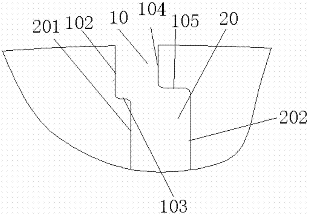
[0024] Such as figure 1 As shown, a rotor punch of a high-speed motor, which includes a body, the body is provided with a plurality of notch structures, the notch structure has a notch 10 and a guide bar groove 20, the guide bar groove 20 One side is provided with a first limiting edge 201, the other side of the guide groove 20 is provided with a second limiting edge 202, one side of the notch 10 has a first notch edge 102, and the notch The other side of 10 has a second notch side 104, the first notch side 102 and the first limiting side 201 and the second notch side 104 and the second limiting side 202 are all in an offset structure, and the first The offset direction between the notch side 102 and the first limiting side 201 is the same as the ...


PUM


Abstract

The invention discloses a rotor stamping of a high-speed motor and a design method thereof. The rotor stamping of the high-speed motor includes a body, and the body is provided with a plurality of notch structures, and the notch structure has a notch and a guide bar groove , one side of the guide bar groove is provided with a first limiting edge, the other side of the guide bar groove is provided with a second limiting edge, one side of the notch has a first notch edge, the The other side of the notch has a second notch side, the first notch side and the first limiting side and the second notch side and the second limiting side are all in an offset structure, and the first notch side and the first limiting side The offset direction between the first limit sides is the same as the offset direction between the second notch side and the second limit side, and the first notch side is connected to the first limit side through the first lateral movement side, The second notch side is connected with the second limiting side through the second traversing side. The invention can improve the mechanical strength of the notch, ensure the leakage reactance of the rotor punch, avoid the deformation of the notch and cause the guide bar to fly out, and reduce the design difficulty of the high-speed motor rotor punch.

Description

technical field [0001] The invention relates to a rotor punch of a high-speed motor and a design method thereof. Background technique [0002] At present, the rotor punching slot adopts a semi-closed slot structure. For high-speed motors, when the motor rotor rotates, the guide bars in the rotor punching slot will generate centrifugal force, which acts on the notch of the rotor punching slot, so the rotor punching The notch design of the sheet needs to consider its mechanical strength. In addition, the rotor notch leakage reactance is an important part of the rotor leakage reactance. When designing the notch of the rotor punching sheet, its influence on the motor rotor leakage reactance must also be considered. [0003] When the mechanical strength of the notch is to be increased by increasing the notch height, the notch width needs to be increased proportionally to ensure the leakage reactance, and the increase in the notch width reduces the contact area between the rotor b...

Claims


Application Information

Patent Timeline
Patent Type & Authority Patents(China)
IPC IPC(8): H02K1/26H02K15/02
Inventor 赵亮姜敞杨钧陈锋吴军
Owner NEW UNITED RAIL TRANSIT TECH
Learn More