Vacuum concentrator

A vacuum concentrator and concentration tank technology, applied in evaporator accessories, chemical instruments and methods, evaporation and other directions, can solve the problems of scaling formation and the reduction of heat transfer efficiency of the concentration tank, so as to prevent the reduction of heat transfer efficiency and reduce heat The effect of consumption

Inactive Publication Date: 2015-12-09
GUANGXI XINLONG PHARMA
View PDF4 Cites 12 Cited by
  • Summary
  • Abstract
  • Description
  • Claims
  • Application Information

AI Technical Summary

Problems solved by technology

[0003] The technical problem to be solved by the present invention is to provide a vacuum concentrator to solve the problem that existing vacuum concentrators are prone to fouling on the wall, resulting in reduced heat transfer efficiency of the concentration tank

Method used


Image

  • Vacuum concentrator
  • Vacuum concentrator
  • Vacuum concentrator

Examples


Embodiment 1

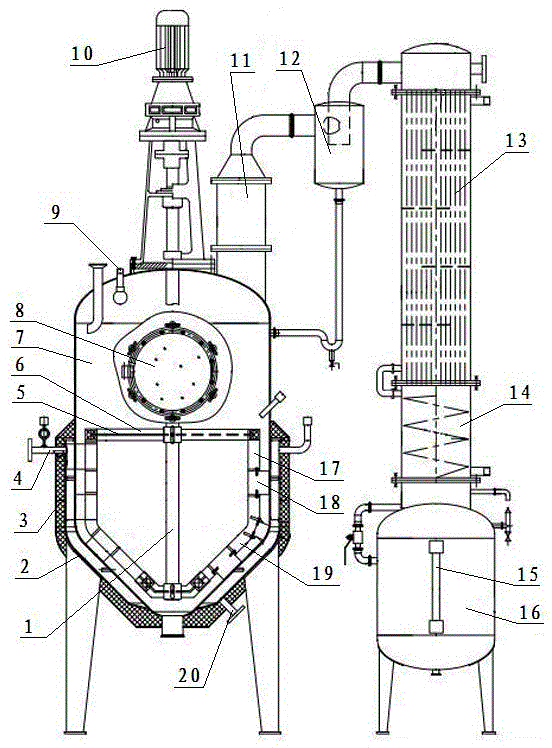
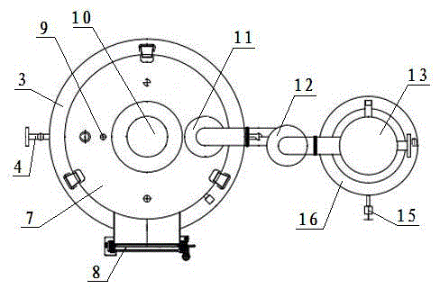
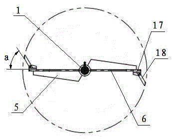
[0017] Such as figure 1 , figure 2 The shown vacuum concentrator includes a concentration tank 7 with a jacket 2 on the outside. The jacket 2 is equipped with a water vapor connecting pipe 4 and a condensed water discharge pipe 20. An insulation layer 3 is installed on the outer surface of the jacket 2. Layer 3 has thermal insulation cotton and a guard plate covering the outer surface of the thermal insulation cotton; the steam outlet of the concentration tank 7 is connected with a vapor-liquid separator 12, a condenser 13, a cooler 14 and a liquid collector 16 in sequence, and the condenser of this embodiment 13 is a shell and tube condenser; a demister 11 is installed between the concentration tank 7 and the vapor-liquid separator 12, and a liquid level gauge 15 is installed on the liquid collector 16; The stirring device connected, the stirring device comprises a rotating shaft 1 and two stirring paddles 5 fixed on the rotating shaft 1, a rotating frame is housed on the r...

Embodiment 2

[0020] The difference between this embodiment and Embodiment 1 is that the angle a between the scraper 18 and the cross bar 6 is 55 degrees. All the other features are the same as in Example 1.


PUM


Abstract

The invention discloses a vacuum concentrator, which relates to the technical field of pharmaceutical equipment manufacturing. The vacuum concentrator comprises a concentrating tank, wherein a jacket is arranged outside the concentrating tank, a vapor-liquid separator, a condenser, a cooler and a liquid collecting device are connected to a vapor outlet of the concentrating tank in sequence, a mixing device which is connected with a motor is installed in the concentrating tank, the mixing device comprises a rotating shaft and at least two mixing paddles which are installed on the rotating shaft, a rotating frame is installed on the rotating shaft, the rotating frame is composed of a V-shaped rod and vertical rods which are connected to both ends of the V-shaped rod, a cross rod is connected between the two vertical rods, and a plurality of scrapers of which the outer sides are abutted with the inner wall of the concentrating tank are installed on the V-shaped rod and the vertical rods. Compared with the prior art, the scrapers of the vacuum concentrator rotate along with the rotating shaft, so as to scrape extract bonded to the inner wall of the concentrating tank, prevent the wall surface from being scaled and prevent the heat transfer efficiency of the concentrating tank from being reduced.

Description

technical field [0001] The invention relates to the technical field of pharmaceutical equipment manufacturing, in particular to a vacuum concentrator. Background technique [0002] Vacuum concentrators are used to concentrate traditional Chinese medicine extracts to prepare large specific gravity extracts. Commonly used vacuum concentrators include a concentration tank with a jacket on the outside. The concentration tank is connected with a vapor-liquid separator, a condenser, a cooler and a liquid collector in sequence. A stirring device connected with a motor is installed in the concentration tank, and the stirring device includes a rotating shaft and two stirring blades fixed on the rotating shaft. This kind of vacuum concentrator has the following disadvantages during use: due to the high viscosity of the extract, it is easy to stick to the inner wall of the concentration tank during the heating and evaporation process, forming scale on the wall surface, resulting in a d...

Claims


Application Information

Patent Timeline
Patent Type & Authority Applications(China)
IPC IPC(8): B01D1/00B01D1/30
Inventor 潘新国
Owner GUANGXI XINLONG PHARMA
Why Eureka
Try Eureka