Annular distributor having guide vane to improve flow rate distribution

a technology of guide rods and distributors, applied in the direction of lighting and heating apparatus, gas-gas reaction processes, physical/chemical process catalysts, etc., can solve problems such as and achieve the effect of lowering heat transfer efficiency

Active Publication Date: 2007-08-30
LG CHEM LTD
View PDF4 Cites 11 Cited by
  • Summary
  • Abstract
  • Description
  • Claims
  • Application Information

AI Technical Summary

Benefits of technology

[0009]The inventors found that the flow of fluid such as heat medium introduced from a duct of a reactor or heat exchanger into a conventional annular distributor creates disturbance caused by collision against an annular layer wall arranged in the inner circumferential surface of the annular distributor and having fluid passage slits. Such disturbance causes nonuniformity to the flow of heat medium, which acts as an obstacle against uniform distribution of heat medium in the annular distributor about the position of the duct, and as a result, flow rate entering the reactor or heat exchanger through a slit opening located on the annular layer becomes ununiform, thereby lowering heat transfer efficiency.
[0010]In order to overcome problems as above, an object of the invention is to provide an annular distributor which has a guide vane capable of improving flow rate distribution of fluid entering or exiting a duct, and thus can improve uniformity of fluid flow without adjustment in the dimension of slits located on an annular slit layer.
[0011]Another object of the invention is to provide an annular distributor which has a guide vane acting as a measure to distribute fluid such as heat medium, and thus can control the amount of fluid entering / exiting according to axial position of a reactor or heat exchanger and concentrate fluid flow to a hot spot where a reaction is violent in order to increase heat transfer efficiency thereby suppressing localized temperature rise.

Problems solved by technology

Such disturbance causes nonuniformity to the flow of heat medium, which acts as an obstacle against uniform distribution of heat medium in the annular distributor about the position of the duct, and as a result, flow rate entering the reactor or heat exchanger through a slit opening located on the annular layer becomes ununiform, thereby lowering heat transfer efficiency.

Method used


Image

  • Annular distributor having guide vane to improve flow rate distribution
  • Annular distributor having guide vane to improve flow rate distribution
  • Annular distributor having guide vane to improve flow rate distribution

Examples


example 1

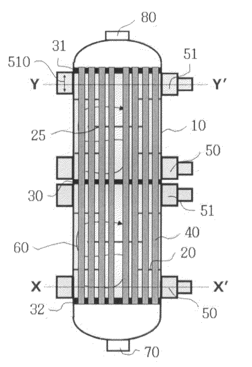
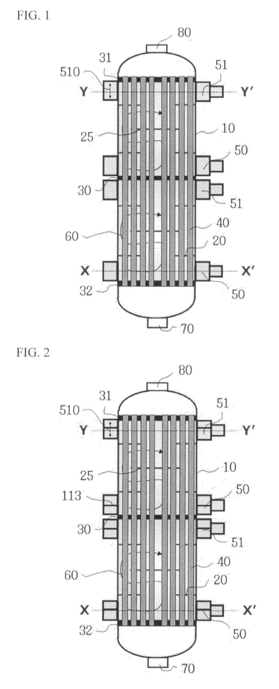
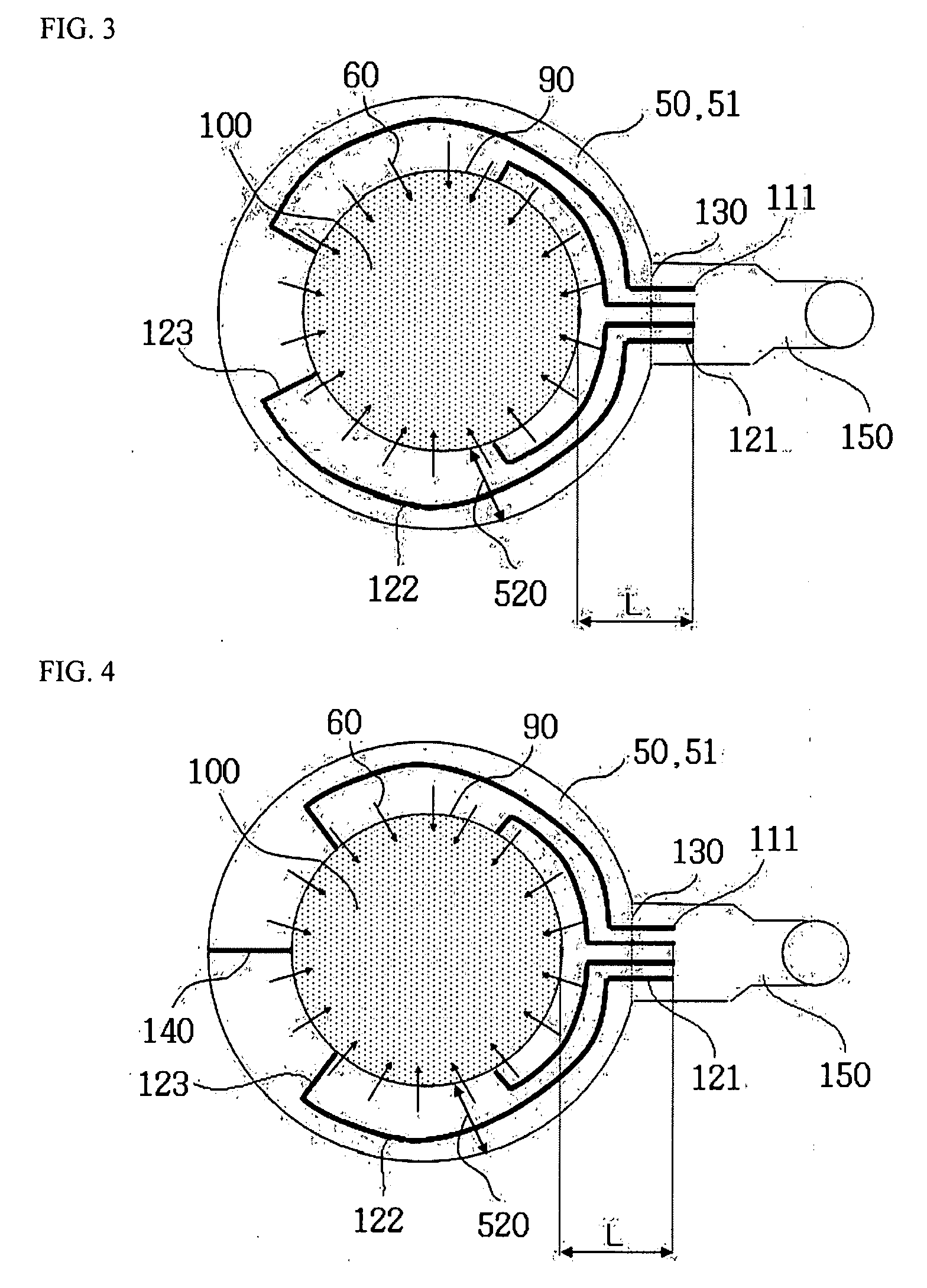
[0141]An annular distributor having an annular slit layer and a first type guide vane as shown in FIG. 4 and a reactor having the same annular distributor were fabricated. The annular distributor and the reactor were set to meet the following dimensions.

[0142]Width of annular distributor (520): 400 mm

[0143]Height of annular distributor (510): 600 mm

[0144]Annular slit layer: single slit layer

[0145]Number of slits: 60

[0146]Width of each slit: 72.43 mm

[0147]Height of each slit: 300 mm

[0148]Starting point of first type guide vane (end of first vertical deflection plate in outer circumferential direction): 1000 mm from inner periphery to outer periphery

[0149]Height of first type guide vane: 600 mm (same as that of annular distributor)

[0150]Number of first type guide vanes: 4

[0151]Shutoff plate: 1, opposite to central axis of opening

[0152]Reactor diameter: 4,150 mm

example 2

[0158]An annular distributor having a slit layer and a second type guide vane as shown in FIG. 7 and a reactor having the same annular distributor were fabricated. The annular distributor and the reactor were set to meet the following dimensions.

[0159]Diameter of slit layer: 4,150 mm

[0160]Height of slit layer: 300 mm

[0161]Width of slit in slit layer: 72.43 mm

[0162]Distribution of slits in slit layer: 6° (angle defined by two adjacent slits with respect to the center of a slit layer circle)

[0163]Width of conduit of annular distributor: 400 mm

[0164]Shape of second type guide vane: triangular prism

[0165]Length of second type guide vane: 1000 mm

example 3

[0170]An annular distributor having a slit layer and a third type guide vane as shown in FIGS. 11 and 14 and a reactor having the same annular distributor were fabricated. The annular distributor and the reactor were set to meet the following dimensions.

[0171]Width of annular distributor (520): 400 mm

[0172]Height of annular distributor (510): 600 mm

[0173]Width of third type guide vane: 400 mm (the same as width of annular distributor)

[0174]Position of third type guide vane: 400 mm point at height of annular distributor (i.e., lower (region A) slit layer height: 400 mm, upper (region B) slit layer height: 200 mm)

[0175]Width of slit in lower (region A) slit layer (230): 72.43 mm

[0176]Height of slit in lower (region A) slit layer (220): region a (100 mm), region b (150 mm), region c (200 mm), region d (100 to 300 mm)

[0177]Width of slit in upper (region B) slit layer (230): 72.43 mm

[0178]Height of slit in upper (region B) slit layer (220): region a (50 mm), region b (100 mm), region c (...


PUM

PropertyMeasurementUnit
radiusaaaaaaaaaa
radiusaaaaaaaaaa
width angleaaaaaaaaaa

Abstract

Disclosed is an annular distributor having: an annular slit layer that is mounted on an inner circumferential surface of the annular distributor and has at least one slit discharging or introducing a fluid; at least one opening that is formed on an outer circumferential surface of the annular distributor and is connected with any one of a fluid supply duct and a fluid discharge duct; and at least one guide vane selected from three types of guide vanes that are installed in the annular distributor, and splits a flow rate of the fluid supplied from the duct or collects a flow rate of the fluid discharged to the duct. And disclosed are a reactor or heat exchanger has the annular distributor, and a method of producing unsaturated aldehyde or unsaturated acid from olefin by catalytic gas phase oxidation in the reactor.

Description

[0001]This application claims the benefit of the filing date of Korean Patent Application Nos. 10-2006-0018268, 10-2006-0031381 and 10-2006-0035936, filed on Feb. 24, 2006, Apr. 6, 2006 and Apr. 20, 2006, respectively in the Korean Intellectual Property Office, the disclosure of which are incorporated herein in their entirety by reference.BACKGROUND OF THE INVENTION[0002]1. Field of the Invention[0003]The present invention relates to an annular distributor having a guide vane to improve flow rate distribution therein, and a reactor or a heat exchanger having the annular distributor.[0004]2. Description of the Related Art[0005]In general, a multitubular catalytic reactor in the form of a heat exchanger is used for the purpose of efficiently removing heat produced in reaction. Such a reactor has solid catalyst filled in a plurality of reaction tubes, and supplies reaction gas into the reaction tubes to create chemical reaction in order to obtain a desired component. In addition, heat ...

Claims


Application Information

Patent Timeline
Patent Type & Authority Applications(United States)
IPC IPC(8): B01J19/00B01J19/26C07C51/16
CPCB01J8/067B01J2208/00221F28F9/0263F28D7/16F28F9/02F28D7/0091
Inventor SHIN, SANG BAEKHAN, SANG PHILIM, YE HOONKIM, YOUNG BAECHANG, JUNG HOON
Owner LG CHEM LTD
Why Eureka
Try Eureka