
powder mixing tank

A mixing tank and powder technology, applied in the direction of dissolution, mixer, chemical instruments and methods, etc., can solve the problems of reduced stirring speed, uneven stirring, and decreased mixing quality, and achieve the effect of improving quality, delicate quality, and uniform mixing

Inactive Publication Date: 2018-06-26
DEQING WEIKANG BIOTECH
View PDF5 Cites 2 Cited by
  • Summary
  • Abstract
  • Description
  • Claims
  • Application Information

AI Technical Summary

Problems solved by technology

[0002] At present, during the stirring process using a solid stirring rod, the stirring is not uniform, and the force-bearing part is fixed, which reduces the stirring quality, and the stirring material is easy to accumulate on the blade, which greatly reduces the stirring speed.

Method used


Image

  • powder mixing tank
  • powder mixing tank
  • powder mixing tank

Examples


Embodiment Construction

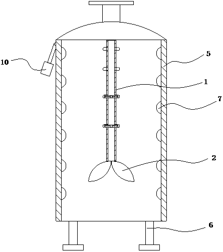
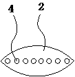
[0015] The present invention as Figure 1-3 As shown, it includes a stirring tank 5, a stirring shaft 1 and a stirring blade 2, the stirring shaft 1 is vertically arranged at the center of the stirring tank 5, the bottom of the stirring tank is provided with a foot 6, and the stirring blade 2 is arranged on the The lower end of the stirring shaft 1; the inner wall of the stirring tank 5 is uniformly provided with elastic protrusions 7 (which can be elastic rubber bodies), and the surface of the stirring tank is movable with a weight 10, which plays a role in moving the elastic protrusions. powder shake off;

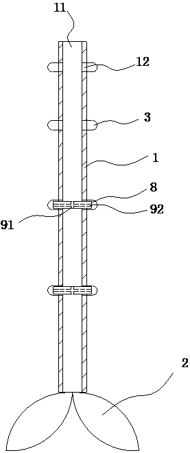
[0016] The stirring shaft 1 has a hollow accommodating chamber 11, the surface of the stirring shaft 1 is uniformly provided with a plurality of stretchable elastic bodies 3, and the side wall of the stirring shaft 1 is provided with through holes communicating with the elastic bodies 3 12. The upper end of the stirring shaft 1 is connected to an air source;

[0017] A ...


PUM


Abstract

Provided is a powder stirring tank with a simple structure and raising the stirring efficiency. The powder stirring tank comprises a stirring tank, a stirring shaft and stirring blades. The stirring shaft is arranged in the center of the stirring tank vertically. The stirring blades are arranged at the lower end of the stirring shaft. Elastic projections are distributed on the inner wall uniformly. A heavy bob is movably arranged on the surface of the stirring tank. The stirring shaft has a hollow holding cavity. A plurality of telescopic elastomers are distributed on the surface of the stirring shaft uniformly. Through holes communicated with the elastomers are arranged in the side wall of the stirring shaft. The upper end of the stirring shaft is communicated with a gas source. The stirring quality is raised greatly, powder is mixed uniformly after stirring, the quality is fine, the structure is simple and usage is convenient.

Description

technical field [0001] The invention relates to the improvement of a powder mixing tank. Background technique [0002] At present, in the stirring process using a solid-state stirring rod, the stirring is not uniform, and the force-bearing part is fixed, so that the stirring quality is reduced, and the stirring material is easy to accumulate on the blade, which greatly reduces the stirring speed. Contents of the invention [0003] Aiming at the above problems, the present invention provides a powder stirring tank with simple structure and improved stirring efficiency. [0004] The technical solution of the present invention is: comprising a stirring tank, a stirring shaft and a stirring blade, the stirring shaft is vertically arranged at the center of the stirring tank, and the stirring blade is arranged at the lower end of the stirring shaft; the inner wall of the stirring tank Elastic protrusions are evenly distributed, and the surface of the mixing tank is movable with...

Claims


Application Information

Patent Timeline
Patent Type & Authority Patents(China)
IPC IPC(8): B01F13/00
Inventor 沈玉田
Owner DEQING WEIKANG BIOTECH
Learn More