Intelligent gear-shifting top-spray shower head
A shower and top spray technology, applied in spraying devices, spraying devices, etc., can solve the problems of high energy consumption, high cost of use, and inability to switch
- Summary
- Abstract
- Description
- Claims
- Application Information
AI Technical Summary
Problems solved by technology
Method used
Image
Examples
Embodiment 1
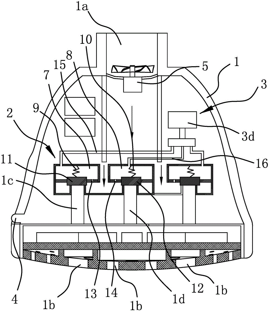
[0036] Such as figure 1 As shown, the intelligent gear shift overhead shower includes a casing 1 with a water inlet 1a on the upper side, several groups of water outlet holes 1b are opened on the bottom of the casing 1, and the number of water outlet holes 1b is the same as that of the groups of water outlet holes 1b. The water outlet chambers are independent of each other, and several water outlet chambers communicate with several groups of water outlet holes 1b in one-to-one correspondence. The casing 1 is also fixed with a pilot structure 2 having a water inlet and several water outlets, a driver 3 capable of driving the pilot structure 2, an inductor 4, and a power supply unit capable of supplying power to the driver 3, wherein the pilot structure 2 The water inlet is connected to the water inlet 1a of the shell 1, the number of the water outlet is the same as that of the water outlet, and the two are connected in one-to-one correspondence. The driving part 3 can drive the...
Embodiment 2
[0045] The structure and working principle of this embodiment are roughly the same as those of Embodiment 1, the difference lies in:
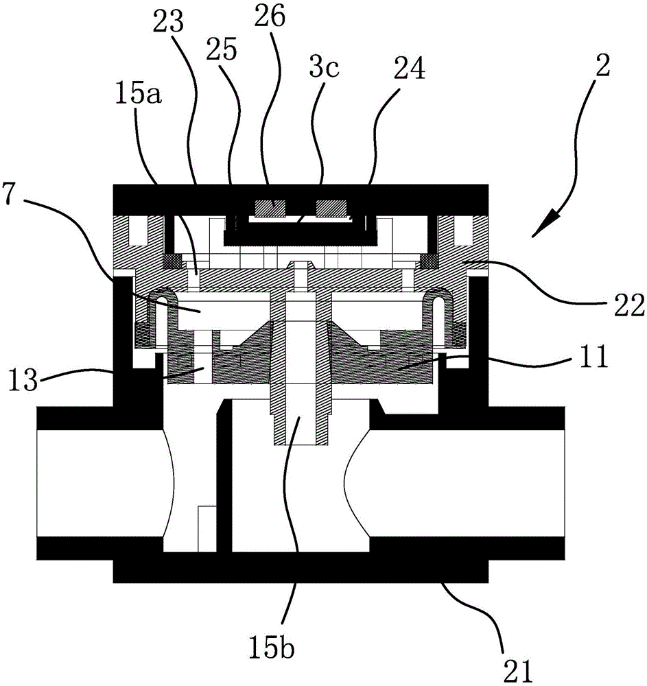
[0046] Such as image 3 As shown, the housing 6 of the pilot structure 2 includes a main body 21 and a middle cover 22 and a top cover 23 both arranged on one side of the main body 21. The main body 21 and the middle cover 22 are hermetically connected and a pressure control chamber is formed between the two. One 7, the gasket one 11 is connected between the middle cover one 22 and the main body 21, and the pressure control chamber one 7 is provided with a spring one 9 (not shown in the figure). The top cover one 23 is in sealing connection with the middle cover one 22 and a pressure relief cavity one is formed therebetween. The pressure relief channel one 15 includes a flow guide hole one 15a and a pressure relief hole one 15b both opened on the middle cover one 22 . Wherein, diversion hole one 15a can communicate with pressure control chambe...
Embodiment 3
[0052] The structure and working principle of the third embodiment are roughly the same as those of the first embodiment, the difference lies in:
[0053] Such as Figure 4 and Figure 5 As shown, the outer wall of the housing 6 of the pilot structure 2 has a concave overflow cavity 17, and the pressure relief channel 15 includes a diversion hole 15a and a pressure relief hole 15b, and the diversion hole 15a can control the pressure Chamber one 7 is connected to the side of the overflow cavity 17 , and the pressure relief hole one 15 b connects the outlet cavity one 1 c to the bottom of the overflow cavity 17 . The driver 3 includes an electric element 3a with a blocking portion that is sealed and connected to the opening of the overflow cavity 17, and the electric element 3a can drive the blocking portion close to the water inlet port of the pressure relief hole 15b under electric drive and block Disconnect pressure relief hole 15b.
[0054] The first pressure control cham...
PUM
 Abstract
Description
Claims
Application Information
 - R&D
- Intellectual Property
- Life Sciences
- Materials
- Tech Scout
- Unparalleled Data Quality
- Higher Quality Content
- 60% Fewer Hallucinations
Browse by: Latest US Patents, China's latest patents, Technical Efficacy Thesaurus, Application Domain, Technology Topic, Popular Technical Reports.
© 2025 PatSnap. All rights reserved.Legal|Privacy policy|Modern Slavery Act Transparency Statement|Sitemap|About US| Contact US: help@patsnap.com


