Upper bending die for forging round crank shaft

A crank and bending technology, applied in the field of bending upper die, can solve the problems of long shaft length, difficult processing, long forging size, etc., and achieve the effect of good length size and good control

Active Publication Date: 2015-12-09
CRRC ZIYANG CO LTD
View PDF6 Cites 0 Cited by
  • Summary
  • Abstract
  • Description
  • Claims
  • Application Information

AI Technical Summary

Problems solved by technology

The traditional curved upper mold cavity is usually designed to have the same outline dimensions as the crank, but there is still a type of round crankshaft whose structure is as follows Figure 1A and Figure 1B As shown, the shape of the crank is circular, that is, the circular crank a, and the height of the circular crank mounting surface b is basically the same as the height of the main journal c. When this type of crankshaft is extruded, the circular crank mounting surface b Prone to forging flash
[0003] Since the crankshaft with the above-mentioned characteristics will have forging flash on the crank mounting surface during the forging process, the bending upper die designed by the traditional design method will have problems such as insufficient extrusion of the single throw and single crank throw when forging the crank throw. The forging size of the forging is longer than the design size, and the length of the whole shaft is too long, which leads to certain difficulties in the processing of the next process, and the high repair rate of rough forgings

Method used


Image

  • Upper bending die for forging round crank shaft
  • Upper bending die for forging round crank shaft
  • Upper bending die for forging round crank shaft

Examples


Embodiment Construction

[0022] All features disclosed in this specification, or steps in all methods or processes disclosed, may be combined in any manner, except for mutually exclusive features and / or steps.

[0023] Any feature disclosed in this specification (including any appended claims, abstract and drawings), unless expressly stated otherwise, may be replaced by alternative features which are equivalent or serve a similar purpose. That is, unless expressly stated otherwise, each feature is one example only of a series of equivalent or similar features.

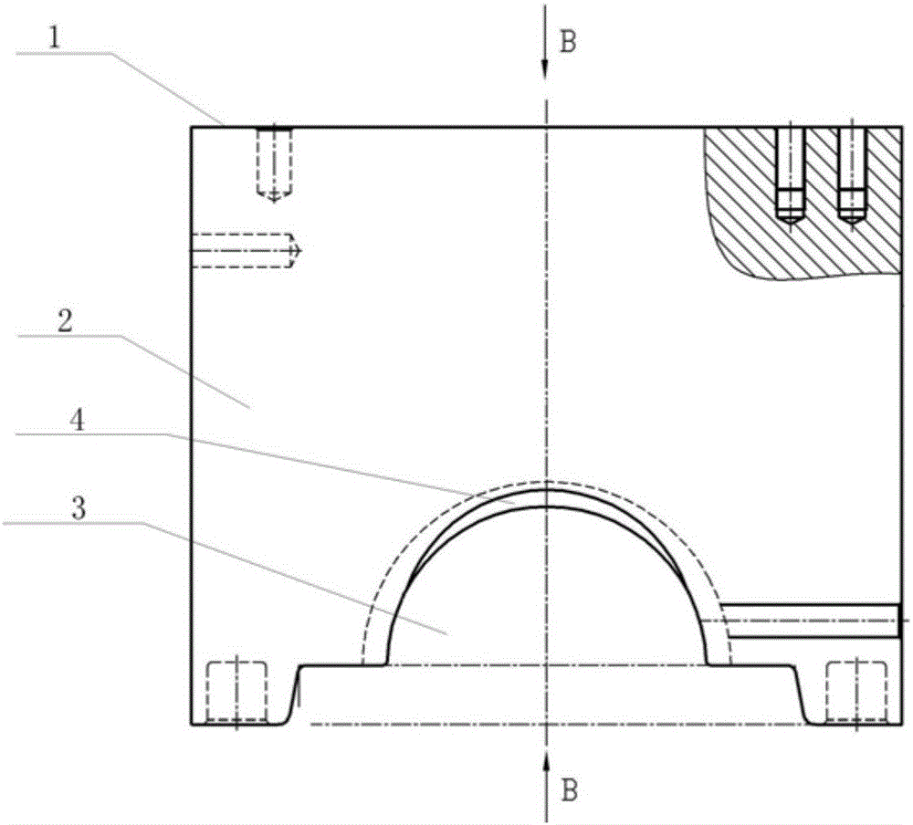
[0024] The structure and principle of the bending upper die for forging the round crank crankshaft of the present invention will be described in more detail below.

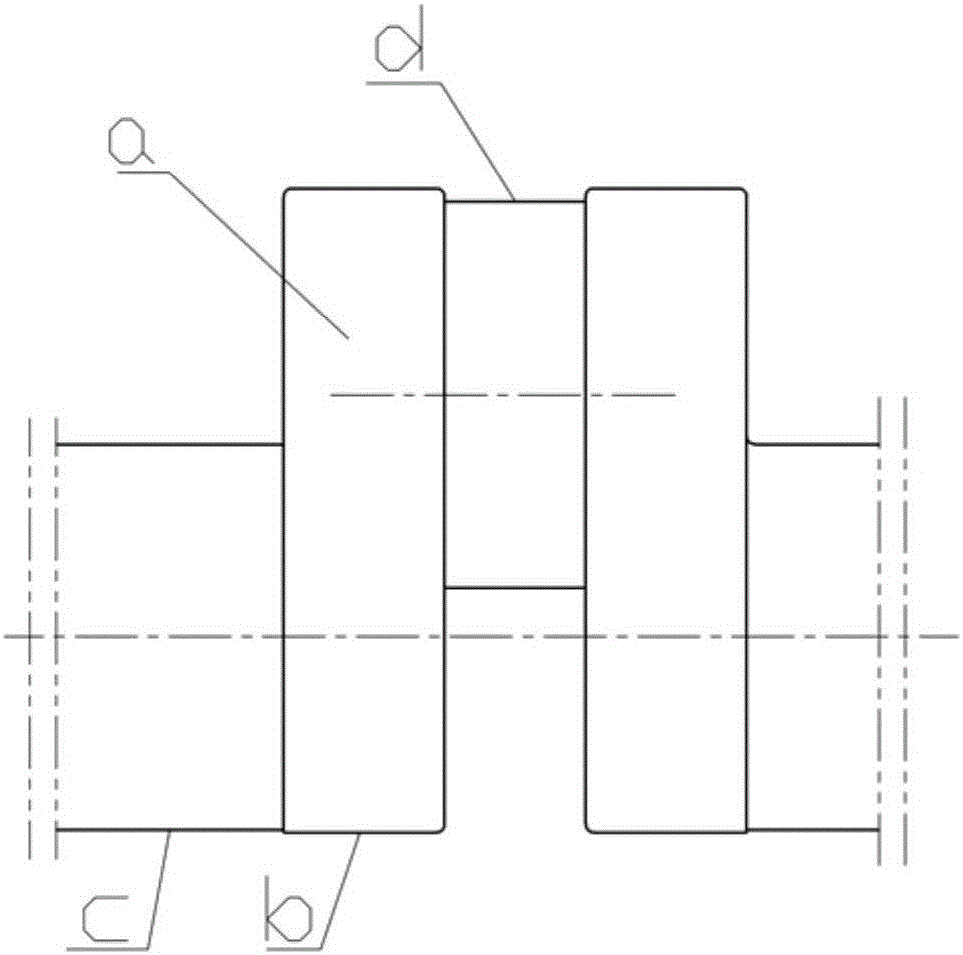
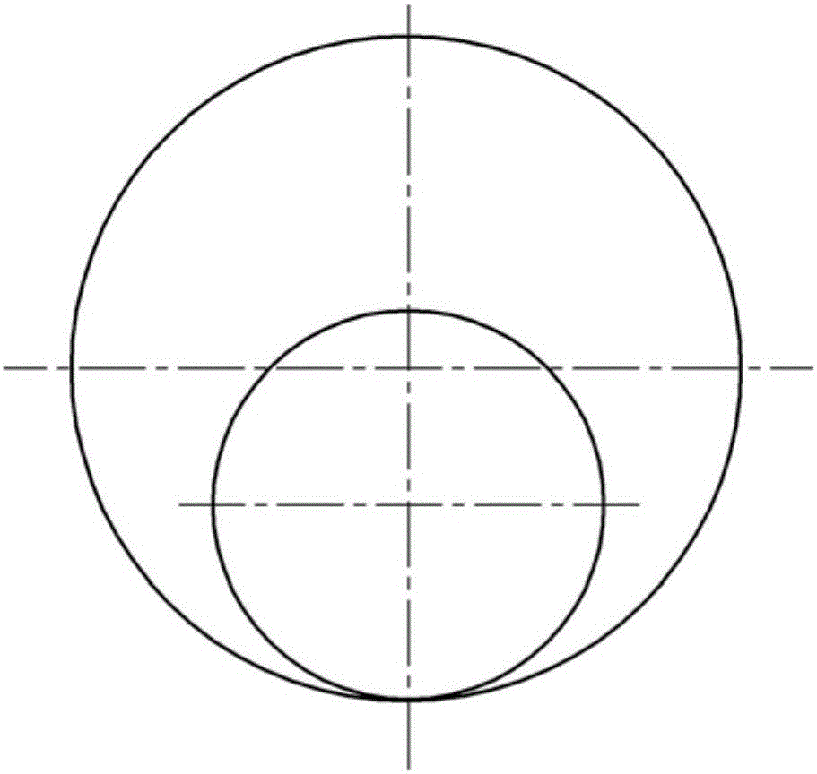
[0025] Figure 1A It shows a schematic diagram of the front view structure of a crank throw of the round crank crankshaft in the present invention, Figure 1B It shows a side view structural schematic diagram of a crank throw of the round crank crankshaft in the present invention...


PUM


Abstract

The invention discloses an upper bending die for forging a round crank shaft. The upper bending die is provided with a die cavity for forging a crank throw in the round crank shaft, wherein the crank throw comprises two round cranks and a connecting rod neck located between the two round cranks. The upper bending die is also provided with a flash groove communicated with the die cavity and used for containing forging flashes of the mounting surfaces of the round cranks. By using the upper bending die for forging the round crank shaft, the forging flashes easily generated in extrusion molding of forging can exactly enter the flash groove, so that each crank throw can be extruded in place when being forged, the single-throw forging size can be controlled and conform to a design size, the length of the whole shaft is favorably controlled, the disposable delivery-check qualified rate of rough forgings is increased, and the quality of each forging is improved.

Description

technical field [0001] The invention relates to the technical field of crankshaft forging dies, in particular to a bending upper die for forging a round crankshaft. Background technique [0002] In the crankshaft forging process technical scheme, the design of the forging die is a key factor affecting the quality of the crankshaft forging. The traditional curved upper mold cavity is usually designed to have the same outline dimensions as the crank, but there is still a type of round crankshaft whose structure is as follows Figure 1A and Figure 1B As shown, the shape of the crank is circular, that is, the circular crank a, and the height of the circular crank mounting surface b is basically the same as the height of the main journal c. When this type of crankshaft is extruded, the circular crank mounting surface b Prone to forging flash. [0003] Since the crankshaft with the above-mentioned characteristics will have forging flash on the crank mounting surface during the ...

Claims


Application Information

Patent Timeline
Patent Type & Authority Applications(China)
IPC IPC(8): B21J13/02B21K1/08
CPCB21J13/02B21K1/10
Inventor 匡利华杜绍贵
Owner CRRC ZIYANG CO LTD
Why Eureka
Try Eureka