
Sprocket pushing mechanism for automatic chain grinding machine

A chain grinding machine and automatic technology, which is applied to the tool dressing, metal processing, metal sawing equipment and other directions of the sawing machine device, can solve the problems of unreasonable principles, affecting the cutting effect, and many parts, etc., and achieves a simple and reasonable mechanism structure. Improve the stability of use and enhance the effect of positioning rigidity

Active Publication Date: 2015-12-09
HANGZHOU SHARP GARDEN MACHINERY
View PDF8 Cites 4 Cited by
  • Summary
  • Abstract
  • Description
  • Claims
  • Application Information

AI Technical Summary

Problems solved by technology

[0004] 1. The chain feeding and pushing tooth mechanism is too complicated, and the transmission process passes through too many parts, which increases the pushing tooth load and cumulative intermittent error
[0005] 2. The principle of pushing the teeth is unreasonable. It cannot guarantee that the length of each tooth after grinding will be consistent, and the inconsistency of the tooth length will lead to the unbalanced load on the left and right during the actual cutting process of the chain saw, which will seriously affect the cutting. Effect
[0006] 3. Many parts (especially belt drives) have cumulative assembly errors and plastic deformation, and the stability and positioning accuracy are very poor during the feeding process, which cannot meet the processing needs
[0007] 4. It is inconvenient to use and debug, has high requirements on the operator, and the adjustment procedure is cumbersome and complicated
[0008] 5. There is no device to automatically detect the left and right knife shapes during the tooth pushing process, which cannot meet the grinding requirements of saw chains with irregularly arranged left and right knife shapes

Method used


Image

  • Sprocket pushing mechanism for automatic chain grinding machine
  • Sprocket pushing mechanism for automatic chain grinding machine
  • Sprocket pushing mechanism for automatic chain grinding machine

Examples


Embodiment Construction

[0022] Describe the embodiment of the present invention in detail below in conjunction with accompanying drawing:

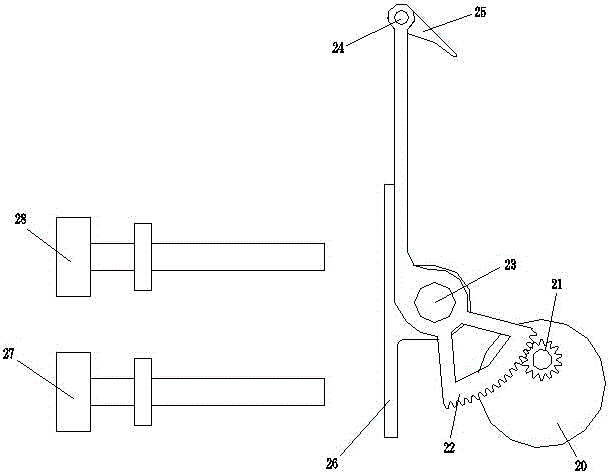
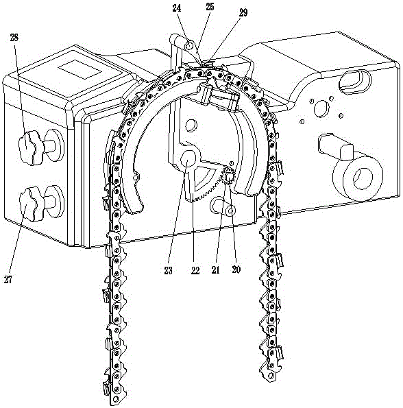
[0023] see Figure 1 ~ Figure 4 , the present embodiment push gear mechanism includes: motor 20, transmission gear 21, swing rod 22, swing rod shaft 23, screw pin 24, push tooth claw 25, limit block 26, grinding position adjustment handle 27, push tooth position adjustment A handle 28 and a housing for installation. The motor 20, the pendulum shaft 23, the grinding position adjustment handle 27, and the push tooth position adjustment handle 28 are all installed on the housing, and the transmission gear 21 is installed on the motor 20 shaft, and the transmission gear 21 meshes with the fan-shaped teeth 221 of the pendulum 22 , the swing rod 22 is rotated and mounted on the swing rod shaft 23 through the swing rod mounting hole 222, the push claw 25 is mounted on the swing rod 22 through the push claw mounting hole 223 and the screw pin 24, and the swing rod 22 is...


PUM


Abstract

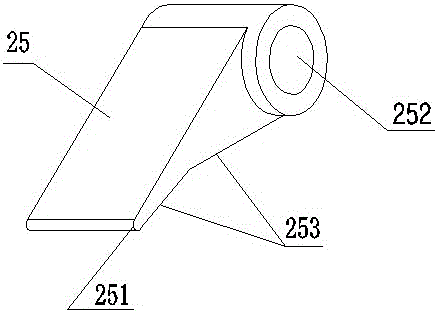
The invention discloses a sprocket pushing mechanism for an automatic chain grinding machine. The sprocket pushing mechanism comprises a motor, a transmission gear, a rocking rod, a rocking rod shaft, a screw pin, a sprocket pushing claw, a limiting block, a grinding position regulating handle, a sprocket pushing position regulating handle and a casing, wherein the motor, the rocking rod shaft, the grinding position regulating handle and the sprocket pushing position regulating handle are respectively mounted on the casing; the transmission gear is mounted on a motor shaft and meshed with fan-shaped teeth of the rocking rod; the rocking rod is mounted on the rocking rod shaft in a rotating manner; the sprocket pushing claw is mounted on the rocking rod in the rotating manner through the screw pin; the rocking rod is fixedly connected with the limiting block; the grinding position regulating handle and the sprocket pushing position regulating handle are respectively corresponding to the limiting block; the sprocket pushing claw is provided with a blocking bevel,a sprocket pushing arc and a screw pin mounting hole, and the screw pin is mounted in the screw pin mounting hole in a sleeved manner. The sprocket pushing mechanism disclosed by the invention is further provided with a sensing and detecting switch for a left sprocket shape and a right sprocket shape, and the sensing and detecting switch for the left sprocket shape and the right sprocket shape is arranged exactly opposite to a saw sprocket at the sprocket pushing position. The sprocket pushing mechanism disclosed by the invention is simple and reasonable in structure, good in rigidity, high in positioning accuracy and simple in regulating manner and can automatically identify the saw sprocket.

Description

technical field [0001] The invention relates to a tooth pushing mechanism for an automatic chain grinding machine, which is used for circularly pushing teeth on a saw chain, and belongs to a component mechanism of the chain grinding machine. Background technique [0002] The saw chain is the cutting part of the chain saw. Its cutting edge is divided into left and right blades and exists in the same saw chain at the same time. The saw chain is a tool used to cut objects. It will become dull after long-term use, resulting in reduced cutting resistance. It is even impossible to cut, so the saw chain teeth need to be ground so that they can continue to meet the needs of the work. Push teeth play an important role in the entire grinding process, the positioning accuracy and rigidity of the push teeth directly determine whether the grinding amount of saw chain teeth can meet the grinding requirements. In the prior art, manual tooth push grinding is usually used, which has problem...

Claims


Application Information

Patent Timeline
Patent Type & Authority Applications(China)
IPC IPC(8): B23D63/16B23D63/12B23Q7/00
Inventor 张文斌王泉福刘国君董琴华
Owner HANGZHOU SHARP GARDEN MACHINERY
Learn More