Small gear rough cutting method for spiral bevel gear

A spiral bevel gear, rough cutting technology, applied to components with teeth, belts/chains/gears, gear teeth, etc., can solve the interference between the back of the knife and the tooth surface, the specification limit of the cutter head, uneven finish cutting allowance, etc. question

Inactive Publication Date: 2015-12-09
CHANGAN UNIV
View PDF7 Cites 9 Cited by
  • Summary
  • Abstract
  • Description
  • Claims
  • Application Information

AI Technical Summary

Problems solved by technology

This method has a great approximation, and the fine cutting allowance is often uneven, and even the interference between the back of the knife and the tooth surface occurs.
In addition, the above two rough cutting methods have strict restrictions on t

Method used


Image

  • Small gear rough cutting method for spiral bevel gear
  • Small gear rough cutting method for spiral bevel gear
  • Small gear rough cutting method for spiral bevel gear

Examples


Embodiment Construction

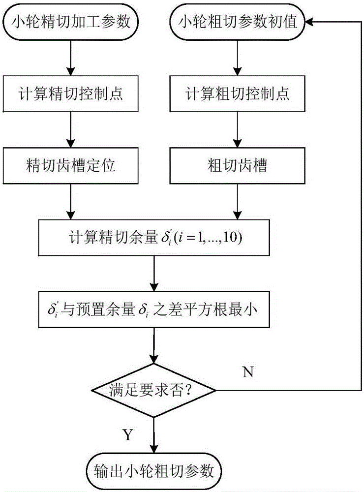
[0046] Such as figure 1 Shown, the pinion rough cutting method of spiral bevel gear of the present invention comprises the following steps:

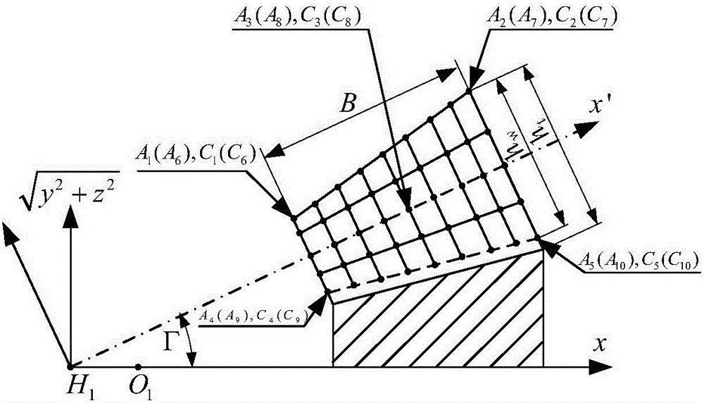
[0047] (1) Knowing the cutter head parameters and machine tool adjustment parameters of the fine-cutting of the small wheel, the tooth surface equations of the concave and convex surfaces of the small wheel can be obtained through the envelope theory and the principle of space meshing; two teeth are respectively taken on the concave and convex surfaces of the small wheel The end point of the top line, the end point of the dividing line between the two working surfaces and the transition surface, and one tooth surface midpoint, a total of 10 fine cutting control points;

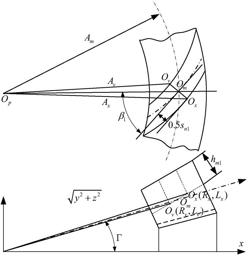
[0048] (2) From the midpoint chord tooth height h of the inspection dimension of the small wheel m1 and midpoint chord tooth thickness s m1 , calculate the positioning angle θ between the concave surface and the convex surface of the small wheel x ; It is stipulated t...


PUM


Abstract

The invention discloses a small gear rough cutting method for a spiral bevel gear. The method comprises the steps that the concave face and the convex face of a small gear are positioned through small gear finishing bevel gear cutter parameters, machine tool adjusting parameters and midpoint checking sizes to obtain a small gear finish cutting gear socket, and coordinates and normal vectors of key points of the two tooth faces are calculated; initial rough cutting machine tool adjusting parameters are given, an equation of the tooth faces on the two sides of the small gear rough cutting gear socket is built, and coordinates of the corresponding key points are obtained; after the midpoint of the small gear rough cutting hear socket is rotated to the midpoint of the small gear finish cutting gear socket, the key points corresponding to the two gear sockets are connected and projected on the normal line of the key points of the finish cutting gear socket to obtain finish cutting allowance; the square root of the difference between the optimized finish cutting allowance and the preset finish cutting allowance is made to be the minimum by optimizing roughing bevel gear cutter parameters or machine tool adjusting parameters. According to the method, the roughing bevel gear cutter specifications can be reduced, the roughing bevel gear cutter and cutter tooth utilization rate is increased, it is ensured that the finish cutting allowance of the tooth faces on the two sides is uniform as much as possible, the follow-up finishing frequency is lowered, and the machining efficiency of the bevel gear is improved.

Description

【Technical field】 [0001] The invention belongs to the technical field of gear transmission, in particular to a small wheel rough cutting method of a spiral bevel gear. 【Background technique】 [0002] Spiral bevel gears include offset hypoid gears and non-offset spiral bevel gears, which are the basic components to realize the motion transmission of intersecting axes. It is used in the fields of automobiles, engineering machinery, rotor-propelled helicopters, machine tools, etc. The essence of bevel gear rough cutting is to open a tooth groove with a certain depth and width on the wheel blank for subsequent finishing. The production efficiency of bevel gears depends on rough cutting. If the margins on both sides of the tooth grooves are uneven or not enough after rough cutting, it will seriously affect the machining accuracy and the service life of the cutter teeth. Cutting is very important, such as Gleason company specially designed and manufactured large wheel, small whe...

Claims


Application Information

Patent Timeline
IPC IPC(8): B23F9/08
Inventor 苏进展郭家舜苏燕芹
Owner CHANGAN UNIV
Why Eureka
Try Eureka