Vertical shot blasting processing machine system for pipe wall surface processing and shot blasting processing method

A technology of surface treatment and treatment method, which is applied in the field of steel pipe treatment, can solve the problems of long time for rust removal, bulky volume, low efficiency, etc., and achieve uniform metallic luster, simple system structure and good treatment effect

Active Publication Date: 2015-12-09
SHANDONG WARMAN MACHINERY TECH +1
View PDF14 Cites 7 Cited by
  • Summary
  • Abstract
  • Description
  • Claims
  • Application Information

AI Technical Summary

Problems solved by technology

[0004] According to the current shot blasting derusting process, to derust the inner and outer walls of the steel pipe, it is usually necessary to use shot blasting machine equipment for derusting the inner and outer walls of the steel pipe separately, and perform shot blasting and derusting operations on the inner and outer walls of the steel pipe respectively. Long rust removal time and low efficiency
[0005] In addition, although the technology for shot blasting and derusting the outer wall of steel pipes is relatively mature in the market, the technology for shot blasting and derusting the inner walls of steel pipes is not yet perfect.
[0006] The existing steel pipe inner wall shot blasting equipment usually adopts a motor-driven hydraulic station, and the hydraulic station drives a hydraulic motor to drive the power transmission mode of the shot blasting head, and since the steel pipe is placed horizontally during the shot blasting process, in order to throw the shot from the The inside of the steel pipe is brought out by a strong air flow, which requires high-power exhaust and dust removal equipment. Therefore, most of the existing shot blasting equipment for the inner wall of the steel pipe is bulky and requires a large workshop space, and has high energy consumption and low rust removal efficiency, especially for large caliber steel pipe
In the process of shot blasting and derusting the inner wall of the existing horizontal steel pipe inner wall, when the pipe diameter is large, the sand shot in the pipe is not easy to be cleaned in time during the shot blasting process, which affects the recycling of the sand shot

Method used


Image

  • Vertical shot blasting processing machine system for pipe wall surface processing and shot blasting processing method
  • Vertical shot blasting processing machine system for pipe wall surface processing and shot blasting processing method

Examples


Embodiment 1

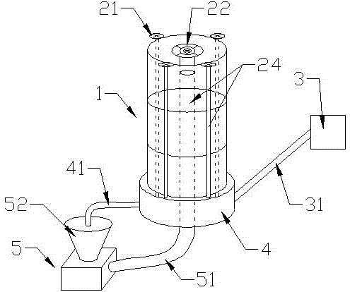
[0042] Example 1, such as figure 1 As shown, the vertical shot blasting treatment machine system for pipe wall surface treatment includes a shot blasting chamber 1, which is a vertically placed cylindrical space structure, which can be specifically made of tubular materials or pipes on the ground or underground. A hollow cylindrical structure surrounded by building materials.

[0043] The shot blasting chamber 1 can be cylindrical or prismatic. In this embodiment, a cylindrical shot blasting chamber is taken as an example for illustration.

[0044] The axial direction of the shot blasting chamber 1 is arranged along the vertical direction, and the axial height of the shot blasting chamber 1 is greater than the diameter of the bottom surface of the shot blasting chamber 1 .

[0045] Below the shot blasting chamber 1, there is a sand shot recovery device 4, which is composed of at least two layers of screens with different apertures, and is used to filter the sundries in the sa...

Embodiment 2

[0060] Embodiment 2, a kind of shot blasting treatment method that is used for pipe wall surface treatment, adopts the vertical shot blasting treatment machine system described in embodiment 1, and described treatment method comprises the following steps:

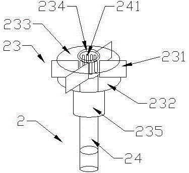
[0061] 1) Shot feeding step: the sand shot pumping device 5 works to transport the sand shot from the bottom of the sand supply pipe 24 to the shot blasting head main body 23 on the top of the sand supply pipe 24 .

[0062] 2) Shot blasting step: when the sand shot reaches the top of the sand supply pipe 24 along the vertical direction of the bottom of the sand supply pipe 24, it enters the shot blasting head blade 231 of the shot blasting head main body 23 through the sand dividing hole 241, and passes through the rotating blasting head. The ball head blade 231 is thrown out in the horizontal direction after being accelerated.

[0063] 3) Recovery step: the sand shot falls into the sand shot recovery device 4 under the sho...


PUM


Abstract

The invention relates to a vertical shot blasting processing machine system for pipe wall surface processing and a shot blasting processing method. A vertical structure is adopted in a shot blasting chamber, and the occupied space is small. An inner shot blasting device is arranged in a cavity of the shot blasting chamber to carry out shot blasting processing on the inner wall of a steel pipe. An outer shot blasting device is arranged on the periphery of the shot blasting chamber, and the inner wall and the outer wall of the steel pipe can be processed at the same time. The shot blasting device comprises a shot blasting head body capable of rotating around a sand supply pipe. A sand distributing hole is formed in the top of the sand supply pipe. When processed sand pellets upwards and vertically arrive at the top of the sand supply pipe from the bottom of the sand supply pipe, the processed sand pellets enter a shot blasting head blade part of the shot blasting head body through the sand distributing hole, and the processed sand pellets are accelerated through rotating shot blasting head blades, and the processing efficiency is high. The processed sand pellets are pumped out through a sand pellet pumping device, and sand supplying is carried out from bottom to top along the sand supply pipe. After processing, the sand pellets can fall into a sand pellet recycling device through gravity of the sand pellets, and the total consumed energy is low; and the structure is simple.

Description

technical field [0001] The invention relates to a shot blasting treatment machine and a treatment method, which are suitable for shot blasting treatment of steel pipe walls, especially for simultaneous shot blasting treatment of the inner and outer walls of steel pipes. Specifically, it relates to a method for surface treatment of pipe walls The vertical shot blasting treatment machine system and the shot blasting treatment method of the present invention belong to the technical field of steel pipe treatment. Background technique [0002] Steel pipes are widely used in the field of water supply. In order to prolong the service life of steel pipes, anti-corrosion treatment is very important. [0003] At present, a relatively advanced anti-corrosion measure is to carry out plastic coating on the inner and outer walls of the steel pipe. The wall of the steel pipe after washing is relatively smooth, which reduces the adhesion of the plastic coating layer on the steel pipe wall....

Claims


Application Information

Patent Timeline
Patent Type & Authority Applications(China)
IPC IPC(8): B24C3/04B24C5/06B24C9/00
CPCB24C3/04
Inventor 杨华杰树贵明
Owner SHANDONG WARMAN MACHINERY TECH
Why Eureka
Try Eureka