Intelligent mobile operation arm having mechanical testing function

A technology for testing functions and mobile operations, applied in the direction of manufacturing tools, manipulators, etc., can solve the problem that the platform cannot realize the coordinated work of the mobile platform and the working manipulator, is not conducive to ensuring the safety of the working mechanism and human, and cannot measure the contact force between the device and the working end. and other issues to achieve the effect of maximizing, protecting people's safety, and achieving work efficiency

Inactive Publication Date: 2015-12-09
HARBIN INST OF TECH
View PDF6 Cites 11 Cited by
  • Summary
  • Abstract
  • Description
  • Claims
  • Application Information

AI Technical Summary

Problems solved by technology

[0005] The purpose of the present invention is to solve the problem that the existing mechanical arm cannot be teleoperated based on visual force feedback, which is not conducive to ensuring the safety of the operating mechanism and human beings; t...

Method used


Image

  • Intelligent mobile operation arm having mechanical testing function
  • Intelligent mobile operation arm having mechanical testing function
  • Intelligent mobile operation arm having mechanical testing function

Examples


specific Embodiment approach 1

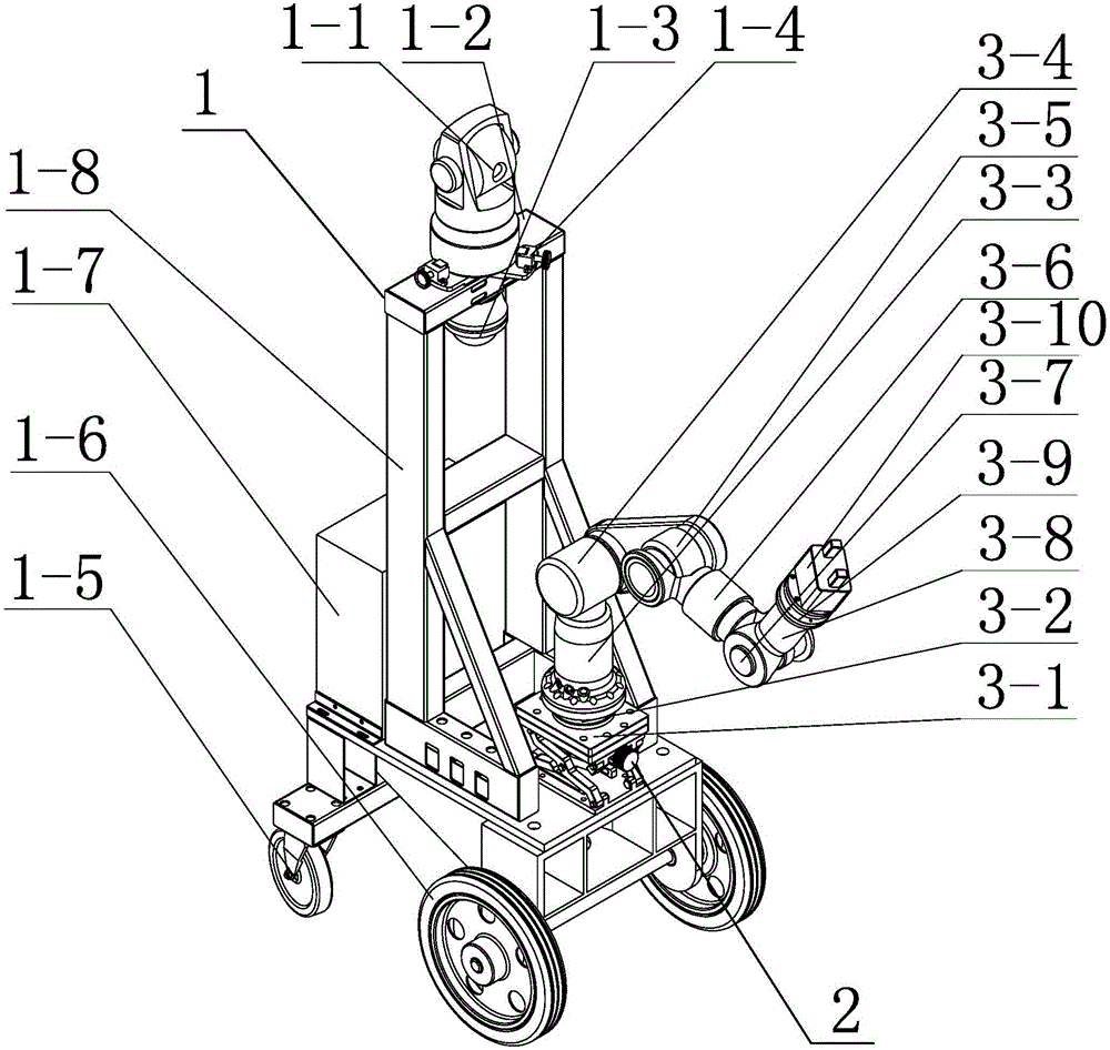
[0016] Specific embodiment one: combine 1 to Figure 8 Describe this embodiment, a kind of intelligent mobile operation arm with mechanical test function of this embodiment comprises mobile platform 1, mechanical arm lifting device 2 and mechanical arm 3, and mechanical arm lifting device 2 is installed on the mobile platform 1 by screw, mechanical The arm 3 is installed on the mechanical arm lifting device 2,

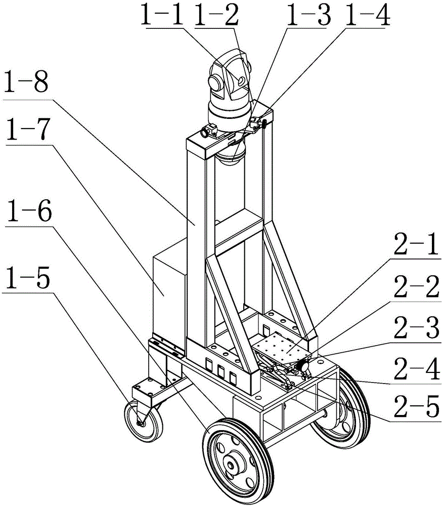
[0017] The mobile platform 1 includes a laser tracker 1-1, a load bracket 1-2, a camera 1-3, a control box 1-7, a platform bracket 1-8 and moving wheels, and the load bracket 1-2 is welded on the platform bracket 1-8 , the laser tracker 1-1 is installed on the upper end of the load bracket 1-2, the camera 1-3 is installed on the lower end of the load bracket 1-2, the control box 1-7 is installed on the side of the platform bracket 1-8, and the moving wheel is installed At the bottom end of the platform support 1-8,

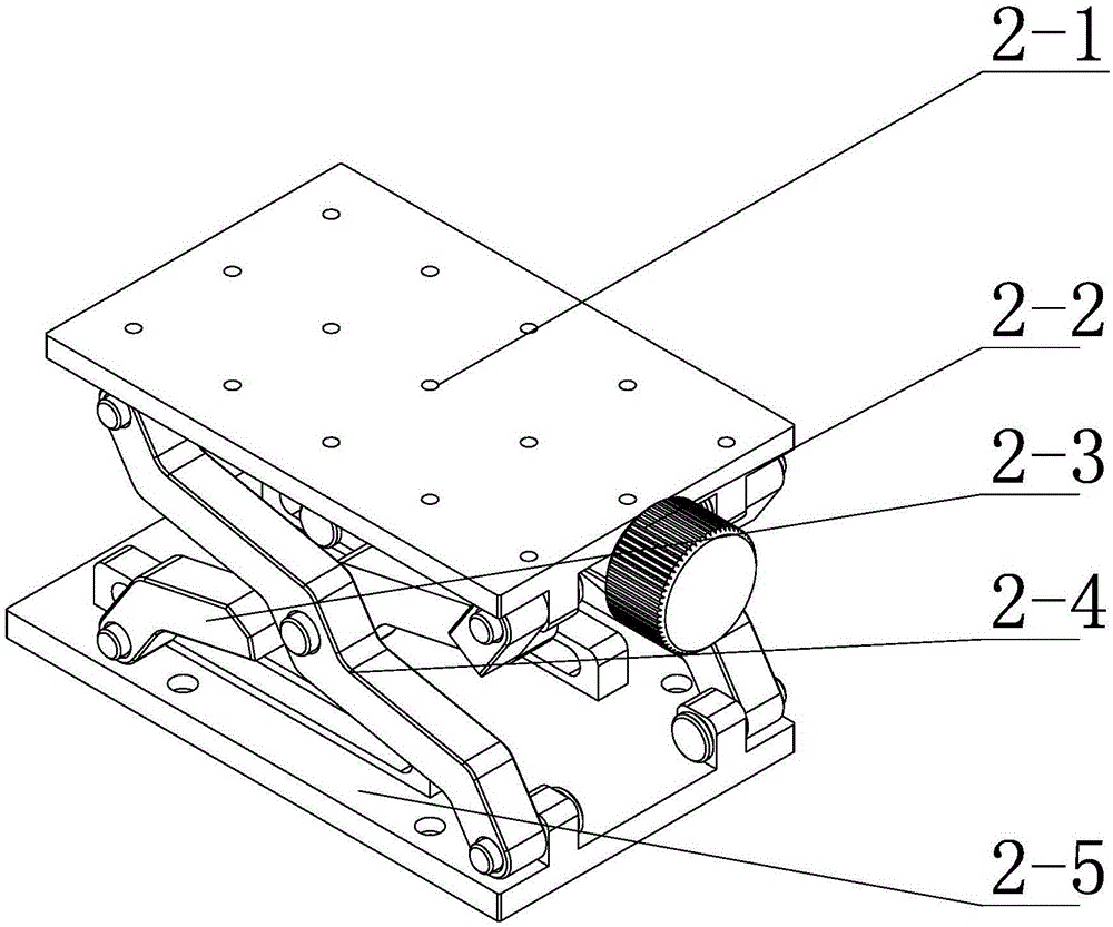
[0018] The mechanical arm lifting device 2 include...

specific Embodiment approach 2

[0021] Specific implementation mode two: combination figure 1 and figure 2 To illustrate this embodiment, the mobile platform 1 of this embodiment further includes a plurality of claw seats 1-4, and the laser tracker 1-1 is installed on the upper end of the load bracket 1-2 through the plurality of claw seats 1-4. It is convenient for connection, and realizes the locking of the laser tracker 1-1. Other compositions and connections are the same as in the first embodiment.

specific Embodiment approach 3

[0022] Specific implementation mode three: combination figure 1 and figure 2 Describe this embodiment, the mobile wheel of this embodiment comprises two front wheels 1-6 and two rear wheels 1-5, and two front wheels 1-6 and two rear wheels 1-5 are installed in sequence from front to back The bottom end of the platform support 1-8. Movement is more flexible. Other compositions and connections are the same as those in the second embodiment.


PUM


Abstract

The invention relates to an intelligent mobile operation arm, in particular to an intelligent mobile operation arm having a mechanical testing function. The problems that an existing mechanical arm cannot perform teleoperation based on visual force, unfavorable for guaranteeing operation mechanism and human safety, contact force of a device and an operation end cannot be measured, the feasibility of the device cannot be judged, and cooperative work of a mobile platform and the operating mechanical arm cannot be achieved are solved. The intelligent mobile operation arm comprises a mobile platform (1), a mechanical arm lifting device (2) and a mechanical arm (3). The mechanical arm lifting device (2) is installed on the mobile platform (1), and the mechanical arm (3) is installed on the mechanical arm lifting device (2). The intelligent mobile operation arm is suitable for robot remote operation, robot mechanical testing and robot information feedback control.

Description

technical field [0001] The invention relates to an intelligent mobile operating arm, in particular to an intelligent mobile operating arm with a mechanical testing function. Background technique [0002] Industrial robots are multi-joint manipulators or multi-degree-of-freedom machine devices for the industrial field. Industrial robots have been widely used in today's society, playing an important role in welding, painting, assembly, collection and placement, product inspection and testing, etc. However, in some environments, such as nuclear power disaster relief, fire and other environments, there are not many applications, and this field still has great research value. [0003] The development and application of industrial mobile robots have been very extensive, and have broad application prospects in factory automation, construction, mining, military, service, agriculture, etc. Mobile robots are mainly divided into crawler, wheel-foot and leg-foot, all of which are wide...

Claims


Application Information

Patent Timeline
IPC IPC(8): B25J5/00B25J13/08
Inventor 丁亮邓宗全夏科睿邢宏军高海波马常友黎佳骏
Owner HARBIN INST OF TECH
Why Eureka
Try Eureka