Mechanical arm

A technology of manipulators and mechanical arms, applied in the field of manipulators, can solve the problems of structural balance of large-sized manipulators, and achieve the effect of shortening the size

Inactive Publication Date: 2015-12-09
HENAN UNIV OF SCI & TECH
View PDF10 Cites 11 Cited by
  • Summary
  • Abstract
  • Description
  • Claims
  • Application Information

AI Technical Summary

Problems solved by technology

[0005] The purpose of the present invention is to provide a manipulator to solve the technical problem in ...

Method used


Image

  • Mechanical arm
  • Mechanical arm
  • Mechanical arm

Examples


Embodiment Construction

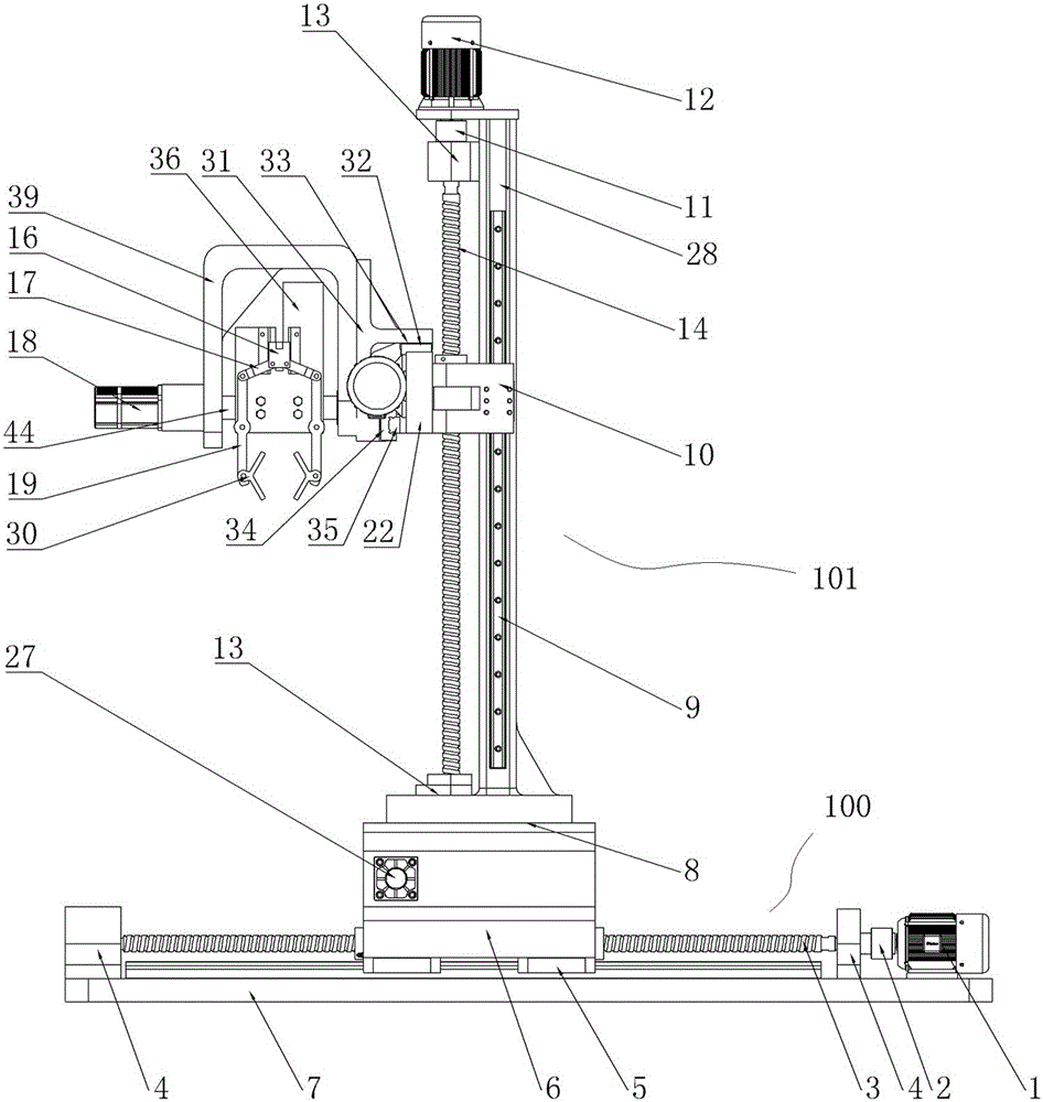
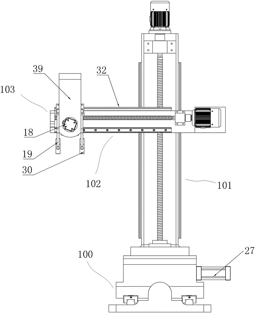
[0029] Embodiment 1 of the manipulator of the present invention, as Figure 2-9 As shown, the manipulator includes a linear arm and a gripper 103. The linear arm includes a first linear arm 100, a second linear arm 101 perpendicular to the first linear arm, and a third linear arm 102 perpendicular to the first and second linear arms. , the first linear arm 100 includes a base 7 whose length extends along the X-axis direction. The two ends of the base 7 are provided with a first lead screw mount 4, and the first lead screw mount 4 is rotatably equipped with a base extending along the X-axis direction. The first lead screw 3, one end of the first lead screw 3 is connected with the first servo motor 1 through the first coupling 2, the first lead screw 3 is movably equipped with a first nut seat 6, and the first nut seat 6 and Between the base 7, a slide rail structure is provided on both sides of the lead screw. The slide rail structure includes a first linear guide rail 20 fixed...


PUM


Abstract

The invention relates to a mechanical arm. The mechanical arm comprises a mechanical arm body and a mechanical claw located at the tail end of the mechanical arm body. The mechanical claw comprises an installing base. The installing base is provided with a mechanical arm clamping claw, a claw driving device used for driving the mechanical arm clamping claw to be closed and opened, and a connecting rod mechanism connected with the mechanical arm clamping claw and the claw driving device. The connecting rod mechanism comprises a sliding block structure driven by the claw driving device to move in a guiding manner in the front and back directions. The sliding block structure is connected with the output end of the claw driving device through a connecting arm. The connecting arm comprises a first connecting section fixedly connected with the output end of the claw driving device and a second connecting section fixedly connected with the sliding block structure. The second connecting section extends in the guiding moving direction of the sliding block structure, and the end, deviating from the first connecting section, of the second connecting section is located on the side, close to the claw driving device, of the first connecting section. The mechanical arm can be used for solving the technical problem that due to the fact that the size of a mechanical claw in the prior art is large, the structural balance of a whole mechanical arm is affected.

Description

technical field [0001] The invention relates to a manipulator, in particular to a manipulator used in an automobile production line. Background technique [0002] With the rapid development of the automobile industry, the application of manipulators in automobile production lines is becoming more and more extensive. For example, the Chinese utility model patent with the authorization announcement date of 2014.08.13 and the announcement number CN203765606U discloses a manipulator. The manipulator includes a base , the mechanical arm and the mechanical claw, the base is fixed on the ground or the workbench, the mechanical arm is fixed on the base, and the mechanical claw is connected to the end of the mechanical arm, wherein the mechanical arm includes a linear arm and a torsion arm, and the linear arm includes a linear arm fixed on the base. The first linear arm on the seat, the second linear arm perpendicular to the first linear arm, and the third linear arm perpendicular to...

Claims


Application Information

Patent Timeline
IPC IPC(8): B25J15/08B25J9/14
Inventor 张丰收李斯文杨星星李鹏飞王团锋徐文静华显伟龚飞单瑞虎
Owner HENAN UNIV OF SCI & TECH
Why Eureka
Try Eureka