Leg configuration for rotatably driven three-dimensional walking robot

A walking robot and rotary drive technology, applied in the field of robots, can solve the problems of power distribution and unevenness of the impact-resistant drive, and achieve the effects of simple structure, light weight of legs, and reduction of mass and rotational inertia.

Active Publication Date: 2015-12-09
SHANGHAI JIAO TONG UNIV
View PDF6 Cites 17 Cited by
  • Summary
  • Abstract
  • Description
  • Claims
  • Application Information

AI Technical Summary

Problems solved by technology

[0006] In view of the above-mentioned deficiencies existing in the prior art, the purpose of the present invention is to provide a three-dimensional walking robot leg configuration driven by rotation, so as to solve the problems that the existing legged robot legs cannot resist impact and the power distribution of the driver is uneven.

Method used


Image

  • Leg configuration for rotatably driven three-dimensional walking robot
  • Leg configuration for rotatably driven three-dimensional walking robot

Examples


Embodiment

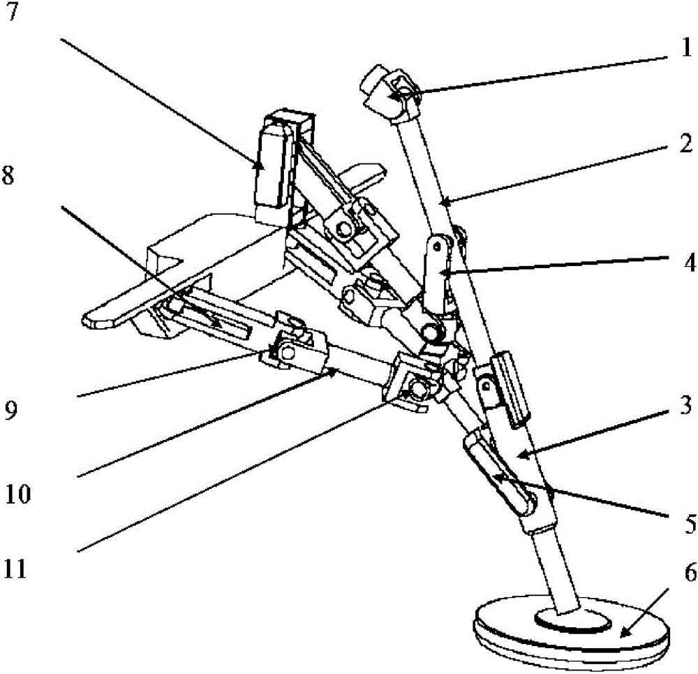
[0038] This embodiment provides a rotationally driven three-dimensional walking robot leg configuration, including: a frame, a leg telescopic mechanism, a parallel drive mechanism, and a rotational drive mechanism; the rotational drive mechanism is drivingly connected to the parallel drive mechanism, and the The parallel driving mechanism is drivingly connected with the leg telescopic mechanism; among them:

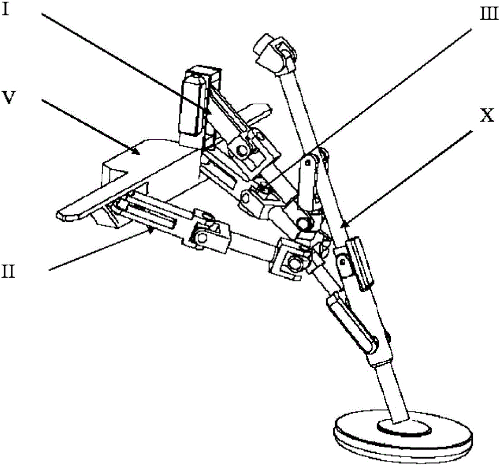
[0039] The side swing block 1 is connected to the frame V through a rotating hinge a to realize the left and right swing of the legs, and then is connected to the swing lever 2 through an orthogonally arranged rotating hinge b to realize the front and back swing of the leg telescopic mechanism. The swing lever 2 passes The rotating hinge c is connected to the transmission rod a4, the transmission rod a4 is connected to the transmission rod b5 through the rotation hinge d, the transmission rod b5 is connected to the calf rod 3 through the rotation hinge e, and the calf rod 3 i...


PUM


Abstract

The invention provides a leg configuration for a rotatably driven three-dimensional walking robot. The leg configuration comprises a rack, a leg telescoping mechanism, a parallel drive mechanism, and a rotatably driven mechanism. The rotatably driven mechanism is connected with the parallel drive mechanism in a driving manner. The parallel drive mechanism is connected with the leg telescoping mechanism in a driving manner. The leg telescoping mechanism is connected with the rack. The leg configuration for a rotatably driven three-dimensional walking robot has special dead point postures, and under the postures, ground impact force stressed by toes cannot be transmitted to a driver, so the robot has very good impact resistance and load resistance capability. The leg configuration solves problems of impact resistance for a robot to work in complex terrain and poor environment operating conditions.

Description

Technical field [0001] The invention relates to the technical field of robots, in particular to a three-dimensional walking robot leg configuration that is rotationally driven against an impact load. Background technique [0002] At present, the research on legged robots has gradually entered the practical stage. There are already many robots that can bring their own energy, walk stably and autonomously outdoors and perform designated tasks. The biggest difference between legged robots and wheeled robots and crawler robots is that legged robots have higher mobility, and they are more suitable for performing tasks in complex terrain, such as chemical plants, earthquake-stricken areas, and nuclear power plants. In order to expand the robot's operating field, it is often necessary to place the robot in these areas in a certain way, and the carrying capacity of the legged structure is often low, especially at the moment the robot hits the ground. How to solve this problem and dispat...

Claims


Application Information

Patent Timeline
Patent Type & Authority Applications(China)
IPC IPC(8): B62D57/032
Inventor 高峰陈先宝郭为忠
Owner SHANGHAI JIAO TONG UNIV
Why Eureka
Try Eureka