
Conveying device

A conveying device and carrier technology, applied in conveyors, mechanical conveyors, transportation and packaging, etc., can solve the problems of large space occupation, high cost, inaccurate conveying positioning, etc., and achieve accurate hovering position and less space occupation. , the effect of convenient transportation

Active Publication Date: 2015-12-09
IXMATION SUZHOU CO LTD
View PDF3 Cites 2 Cited by
  • Summary
  • Abstract
  • Description
  • Claims
  • Application Information

AI Technical Summary

Problems solved by technology

[0003] The traditional circular conveying device generally has the following problems. First, the complex structure takes up a lot of space and high cost. It needs to use multiple guide rails and conveyor belts. The connecting parts of multiple guide rails and conveyor belts need to use a rotary device, resulting in a lot of wasted space. The production cost of the conveying device is increased; second, the carrier is in direct contact with the belt, and the load on the belt is large. When the belt route is uneven, it will also cause damage to the belt, and it is prone to bumps, which will cause the workpiece to shift; third The conveying positioning is inaccurate, the positioning accuracy of the hovering equipment is low, and problems such as misalignment and deviation often occur

Method used


Image

  • Conveying device
  • Conveying device

Examples


Embodiment Construction

[0025] The present invention will be described in detail below in conjunction with specific embodiments shown in the accompanying drawings. However, these embodiments are not limited to the present invention, and structural, method, or functional changes made by those skilled in the art according to these embodiments are included within the protection scope of the present invention.

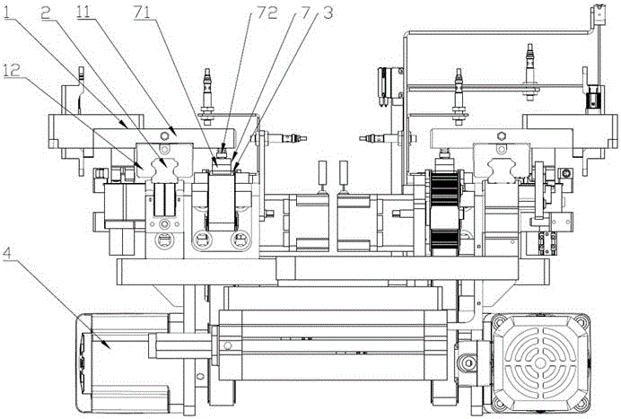
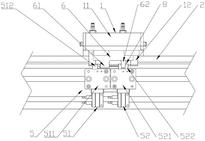
[0026] like figure 1 and figure 2 As shown, a conveying device includes a carrier 1, a guide rail 2 for carrying the carrier 1, a belt 3 for driving the carrier 1, a power mechanism 4 as a power source for the belt 3, and a device for blocking the carrier 1. The positioning mechanism 5 of the position, the guide rail and the belt are ring-shaped, and the best is the shape of a football field runway, so that the conveying device forms an annular circulation conveying structure. The power mechanism 4 is preferably a rotor motor, and the rotor motor is driven and connected with the belt 3; Wherein...


PUM


Abstract

The invention discloses a conveying device. The conveying device comprises a carrier, a guide rail, a belt, a power mechanism and a positioning mechanism. The carrier is composed of a carrying table, a sliding block, a limiting assembly and a pressing plate assembly and arranged on the guide rail in a sliding mode through the sliding block. The pressing plate assembly abuts against the belt, and friction force between the pressing plate assembly and the belt is larger than that between the sliding block and the guide rail. The carrier is in a suspended state or a moving state under the action of the positioning mechanism. The conveying device has the advantages that the guide rail plays a role in supporting, so that loads on the belt are reduced; meanwhile, the friction force between a pressing block and the belt is larger than that between the sliding block and the guide rail, so that conveying is convenient and flexible, and the structure is ingenious; the positioning mechanism is provided with a stopping part and a positioning part, the stopping part performs stopping, and then the positioning part performs accurate positioning, so that the suspending position of the carrier is more accurate through secondary positioning; the guide rail and the belt are in a cyclic ring shape, so that cyclic conveying is achieved; just one guide rail and one belt are needed, so that the conveying device is simple in structure, small in occupied space and low in cost.

Description

technical field [0001] The invention relates to a conveying device, in particular to a conveying device with simple structure and flexible conveying. Background technique [0002] With the continuous development of industrial production, the degree of automation is getting higher and higher. Various conveying devices are involved in the production process of the factory, and the conveying devices are divided into one-way conveying devices and circular conveying devices. [0003] The traditional circular conveying device generally has the following problems. First, the complex structure takes up a lot of space and high cost. It needs to use multiple guide rails and conveyor belts. The connecting parts of multiple guide rails and conveyor belts need to use a rotary device, resulting in a lot of wasted space. The production cost of the conveying device is increased; second, the carrier is in direct contact with the belt, and the load on the belt is large. When the belt route is...

Claims


Application Information

Patent Timeline
IPC IPC(8): B65G37/00
Inventor 宗小进郑理权倪前磊牛丽
Owner IXMATION SUZHOU CO LTD
Learn More