Rotary ball-seat hydraulic impact discharging device

A flusher and ball seat type technology, which is applied in the field of pretreatment equipment in the sugar industry, can solve the problems of excessive recoil and inconvenient control, and achieve the effect of convenient control and wide coverage angle

Inactive Publication Date: 2015-12-09
NANNING LIHAN INSTR EQUIP CO LTD
View PDF6 Cites 2 Cited by
  • Summary
  • Abstract
  • Description
  • Claims
  • Application Information

AI Technical Summary

Problems solved by technology

[0006] The purpose of the present invention is to solve the problems of excessive recoil and inconvenient control of existing hydraulic flushers, and to provide an easy-to-manipulate rotating ball-seat hydraulic flusher

Method used


Image

  • Rotary ball-seat hydraulic impact discharging device
  • Rotary ball-seat hydraulic impact discharging device

Examples


Embodiment 1

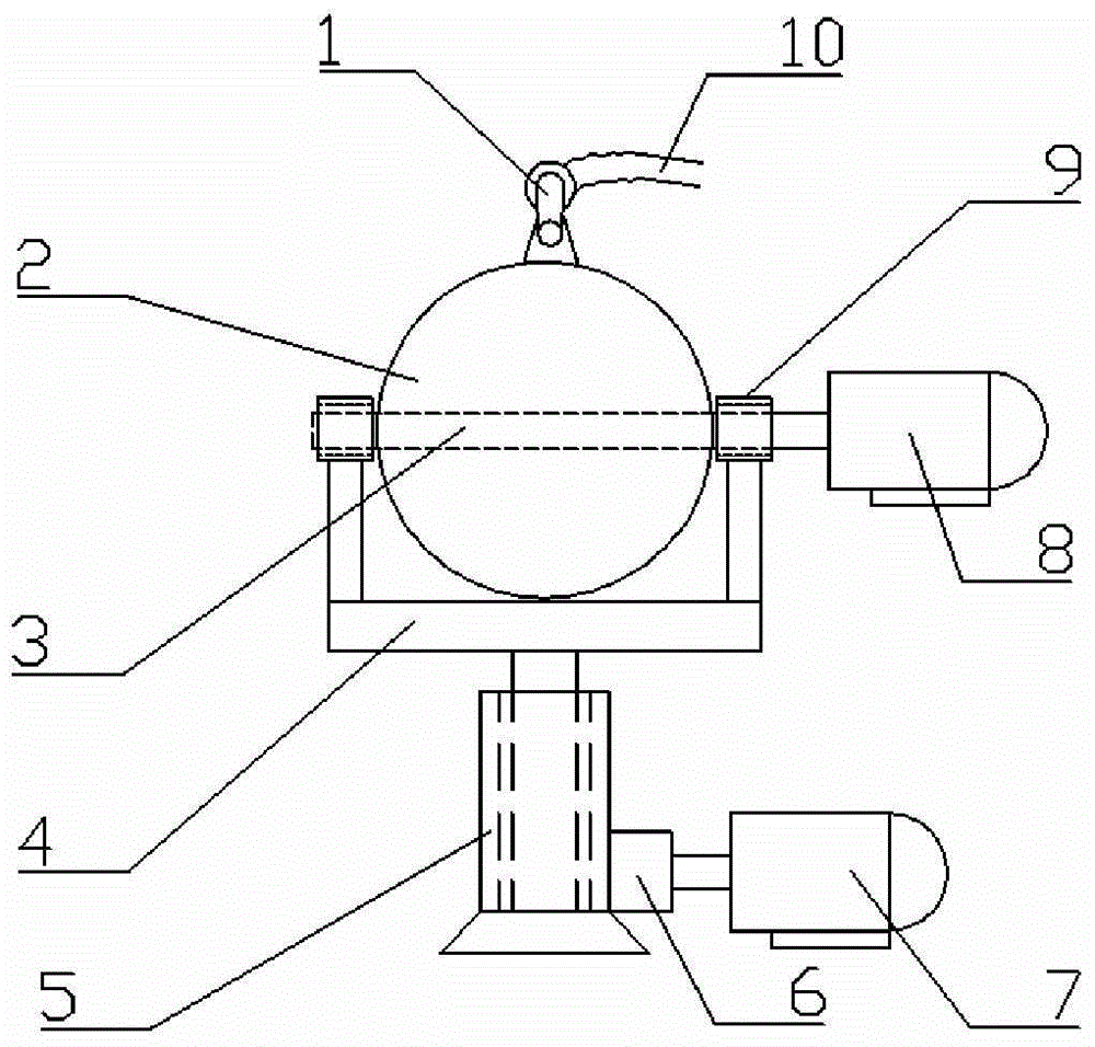
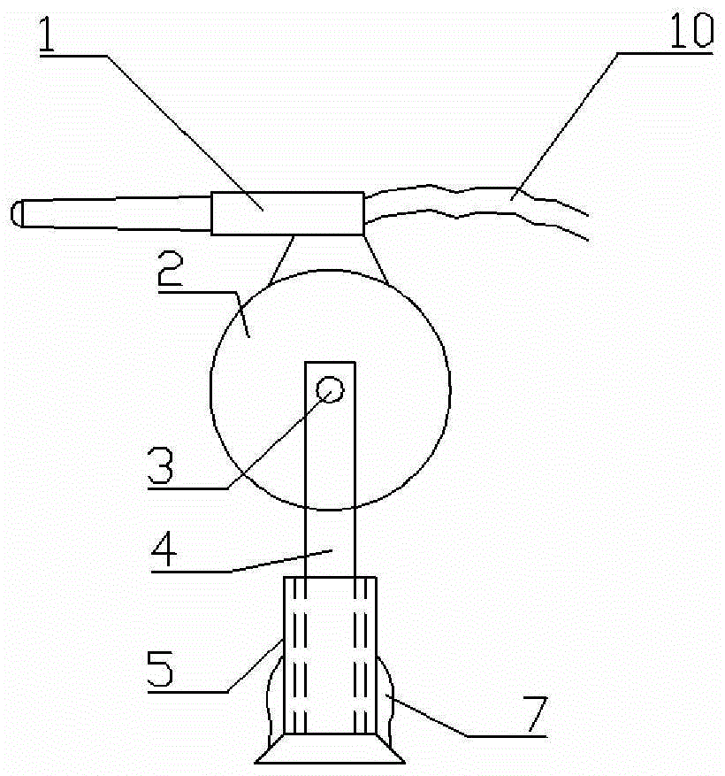
[0024] Embodiment 1: see figure 1 with figure 2 , a rotating ball seat type hydraulic flushing device, comprising a high-pressure spray gun 1, a spherical base 2, a horizontal rotating shaft 3, and a support frame 4, the high-pressure spray gun 1 is installed on a spherical base 2, and the spherical base 2 is movably supported by the support frame 4, and the high-pressure The water inlet pipe 10 is connected to the injection port of the spray gun 1; the horizontal rotating shaft 3 passes through the center of the spherical base 2 and is integrally formed with the spherical base, and the two ends of the horizontal rotating shaft 3 are provided with bearings 9; the spherical base 2 is installed on the support frame 4 through the bearings 9 , and can rotate horizontally around the horizontal rotating shaft 3; an extension is fixed below the support frame 4, and the extension falls into the sleeve 5 arranged on the ground, and the entire support frame 4 can rotate vertically arou...

Embodiment 2

[0026] Embodiment 2: This embodiment is a further improvement made on the basis of Embodiment 1, and its difference from Embodiment 1 is that: one end of the horizontal rotating shaft 3 is directly fixedly connected with the power output shaft of the horizontal rotation motor 8; The extension of the support frame 4 is connected with the power output shaft of the vertical rotation motor 7 through the transmission 6 . The transmission 6 is a reversing gear set, and the lower end of the extension of the support frame 4 is fixed with gears corresponding to the reversing gear set. The shell of the spherical base 2 is an iron sheet, and the inside is evenly poured with concrete. The high-pressure spray gun 1 is arranged on the top of the spherical base 2, and is fixedly connected with the spherical base 2 through an angle connector of 50 to 80°. The sleeve 5 is installed on the operating platform near the sugar beet flow ditch. The performance of the hydraulic flusher in this embo...

Embodiment 3

[0027] Embodiment 3: This implementation is a further improvement made on the basis of Implementation 2. The difference between it and Embodiment 1 is that the vertical rotation motor 7 and the rotation motor 8 are variable frequency motors, and are connected to the control center through the data transmission channel connected, remotely controlled by the control center.


PUM


Abstract

The invention relates to the field of pretreatment equipment in sugar making industry, and discloses a rotary ball-seat hydraulic impact discharging device which comprises a high-pressure spray gun, a ball seat, a horizontal rotating shaft and a supporting frame, wherein the high-pressure spray gun is installed on the ball seat; the ball seat is flexibly supported by the supporting frame; an injection port of the high-pressure spray gun is connected with a water inlet pipe; the horizontal rotating shaft penetrates through the center of the ball seat and is integrally formed with the ball seat; both ends of the horizontal rotating shaft are provided with bearings; the ball seat is installed onto the supporting frame through the bearings, and can horizontally rotate around the horizontal rotating shaft; an extension part is fixed to the lower part of the supporting frame, and falls into a sleeve arranged on the ground; the whole supporting frame can vertically rotate around the sleeve; the horizontal rotating shaft and the extension part of the supporting frame are respectively connected with a horizontal motor and a vertical motor in a driving mode; and the dead weight of the ball seat is 3-10 times of the maximum recoil force borne by the high-pressure spray gun. The rotary ball-seat hydraulic impact discharging device has the characteristic of small recoil force, and is convenient to control.

Description

technical field [0001] The invention relates to the field of pretreatment equipment in the sugar industry, in particular to a hydraulic flusher. Background technique [0002] The hydraulic unloader is a common equipment in the beet sugar industry. It is a device that uses water with a certain pressure to unload the beets into the flow channel. The most basic working part of the hydraulic unloader is a high-pressure water gun. The traditional hydraulic flushing device needs to be controlled manually, that is, the operator stands in the working area and holds the hydraulic flushing device, constantly adjusting the angle of the high-pressure jet to flush the sugar beets. Operators not only have to endure the invasion of water mist like this, but also have to overcome the recoil force of the hydraulic flusher with all their strength. The working environment is harsh and the operation is difficult. [0003] The domestic patent database also discloses some related technologies of...

Claims


Application Information

Patent Timeline
Patent Type & Authority Applications(China)
IPC IPC(8): B65G67/04B65G51/01
Inventor 陈黔梁勤曾淮海聂军黄志柯黄谨张华清黄德霄李福琉梁卫
Owner NANNING LIHAN INSTR EQUIP CO LTD
Why Eureka
Try Eureka