Clamping tool for components to be quenched

A technology for clamping tooling and components, applied in the field of heat treatment, can solve the problems of loose fixation and inflexible operation, and achieve the effects of high machining accuracy, simple principle and simple structure

Inactive Publication Date: 2015-12-09
TIANJIN HEAT TREATMENT INST
View PDF0 Cites 0 Cited by
  • Summary
  • Abstract
  • Description
  • Claims
  • Application Information

AI Technical Summary

Problems solved by technology

[0004] In view of this, the present invention aims to propose a clamping tool for quenched parts to solve the problems of loose fixation and inflexible operation during processing

Method used


Image

  • Clamping tool for components to be quenched

Examples


Embodiment Construction

[0017] It should be noted that, in the case of no conflict, the embodiments of the present invention and the features in the embodiments can be combined with each other.

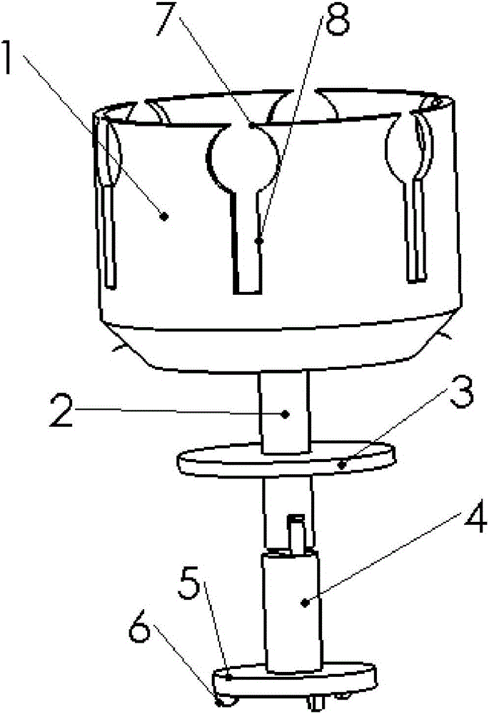
[0018] A clamping tool for quenched parts, comprising a cylindrical body 1 with grooves, the outer wall of the body 1 is provided with several circular adjustment ports 7 along the circumference, and the body 1 below each adjustment port 7 There is a rectangular adjustment slot 8 on it;

[0019] A support rod 2 is provided at the center of the lower end surface of the body 1 , and the support rod 2 is supported on the support plate 5 .

[0020] The support rod 2 runs through the center of the turntable 3 .

[0021] The lower end of the support rod 2 is hinged to the upper end of the hinged rod 4 , and the lower end of the hinged rod 4 is fixed at the center of the support plate 5 .

[0022] The lower end surface of the support disc 5 is provided with three rollers 6 evenly arranged in the circumferential d...


PUM


Abstract

The invention provides a clamping tool for components to be quenched. The clamping tool comprises a cylindrical body. The body is provided with a groove, a plurality of round adjusting openings are formed in the outer wall of the body in the peripheral direction, and a rectangular adjusting groove is formed in the part, below each adjusting opening, of the body. A supporting rod is arranged in the center of the lower end surface of the body and on a supporting plate in a supported mode. The supporting rod penetrates through the center of a rotation plate, the lower end of the supporting rod is hinged to the upper end of a hinging rod, and the lower end of the hinging rod is fixed to the center of the supporting plate. Three idler wheels are uniformly arranged on the lower end surface of the supporting plate in the peripheral direction. The clamping tool for the components to be quenched is simple in structure and principle. A groove in a sleeve is used for clamping the components and can meet the requirement of metal elasticity so that the extension space in the stressing space can be enough, the components can be clamped tightly and the machining accuracy of the components to be quenched can be high.

Description

technical field [0001] The invention belongs to the technical field of heat treatment, and in particular relates to a clamping tool for quenched parts. Background technique [0002] Quenching process is widely used in modern machinery manufacturing industry. The important parts in machinery, especially the steel parts used in automobiles, airplanes and rockets, are almost all quenched. In order to meet the technical requirements of various parts, various quenching processes have been developed. For example, according to the part to be treated, there are overall, local quenching and surface quenching; according to whether the phase transformation is complete during heating, there are complete quenching and incomplete quenching (for hypoeutectoid steel, this method is also called subcritical quenching); according to cooling The content of time phase transformation includes graded quenching, austempering and underspeed quenching. [0003] At present, the quenching fixtures o...

Claims


Application Information

Patent Timeline
Patent Type & Authority Applications(China)
IPC IPC(8): C21D1/62
Inventor 王宝平曹家兴
Owner TIANJIN HEAT TREATMENT INST
Why Eureka
Try Eureka