Rail plate locking seat of magnetic levitation rail

A technology of magnetic levitation and locking seat, applied in the directions of track, laying track, track maintenance, etc., can solve the problems of complex structure of the magnetic levitation rail plate locking seat, inconvenient assembly and disassembly, etc., and achieves simple structure, convenient assembly and disassembly, and strong applicability Effect

Active Publication Date: 2015-12-09
ANHUI XINGYU TRACK EQUIP
View PDF7 Cites 4 Cited by
  • Summary
  • Abstract
  • Description
  • Claims
  • Application Information

AI Technical Summary

Problems solved by technology

[0003] The purpose of the present invention is to solve the technical problems of complex structure and inconvenient assembly and disassembly of the magnetic levitation rail plate locking seat in the prior art, and provide a rail plate locking seat of the magnetic levitation track

Method used


Image

  • Rail plate locking seat of magnetic levitation rail
  • Rail plate locking seat of magnetic levitation rail

Examples


Embodiment Construction

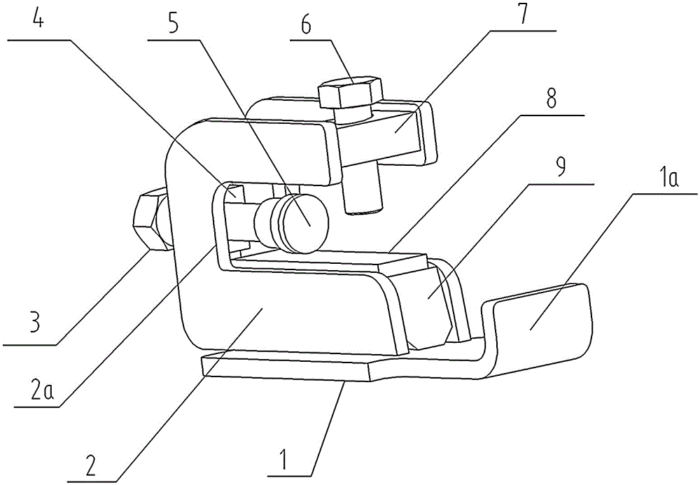
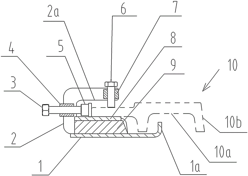
[0015] like figure 1 , figure 2 As shown, the rail plate locking seat of a magnetic levitation track provided by the present invention includes a base plate 1, a pair of vertical plates 2 are arranged on the base plate, a support block 9 is provided on the base plate between the vertical plates, and a support block 9 is provided with The backing plate 8 is respectively provided with an opening groove 2a matching with the F-shaped rail plate 10 on one side of the corresponding vertical plate 2, and one side of the F-shaped rail plate 10 is placed in the opening groove 2a, and its bottom is slidably matched with the top of the backing plate 8, A section of the base plate 1 is a vertically upward bending section 1a, which is placed in the track groove 10a of the F-shaped rail plate and forms a limiting fit with the two wings 10b of the F-shaped rail plate; The first connecting plate 7 is arranged between the corresponding vertical plates 2, and the first connecting plate is pro...


PUM


Abstract

The invention relates to a rail plate locking seat of a magnetic levitation rail. The rail plate locking seat is characterized by comprising a base plate (1). A pair of vertical plates (2) are arranged on the base plate, and one sides of the vertical plates are provided with opening grooves (2a) matched with an F type rail plate (10). The rail plate locking seat has the advantages that the structure is simple, mounting and demounting are convenient, the manufacturing cost is low, high adaptability is achieved, and the rail plate locking seat can be installed on magnetic levitation rail plates with different specifications.

Description

technical field [0001] The invention relates to the field of a rail plate adjustment device for a magnetic levitation track, in particular to a rail plate locking seat for a magnetic levitation track. Background technique [0002] The maglev railway track is mainly composed of subgrade, bridge, concrete base and rail row. After the concrete foundation of the subgrade is built, the rail row is installed and adjusted section by section according to the design requirements of the maglev track line and the track paving sequence table. When adjusting the longitudinal, horizontal and elevation of the rail row, since the adjuster cannot be directly connected to the rail plate, it needs to be connected to the F-shaped rail plate through the locking seat. At present, the existing rail plate locking seat has complex structure, inconvenient loading and unloading, and takes up a lot of time for rail adjustment. Contents of the invention [0003] The purpose of the present invention i...

Claims


Application Information

Patent Timeline
Patent Type & Authority Applications(China)
IPC IPC(8): E01B29/02
Inventor 薛恒鹤钟良周会
Owner ANHUI XINGYU TRACK EQUIP
Why Eureka
Try Eureka