Microfluidic valve and microfluidic chip

A microfluidic and valve technology, applied in the field of microfluidics, can solve the problems of inconvenient assembly, many microfluidic chip components, and complex microfluidic chip structure, and achieve the effect of facilitating assembly and reducing the number of components

Active Publication Date: 2015-12-09
CAPITALBIO CORP
View PDF12 Cites 15 Cited by
  • Summary
  • Abstract
  • Description
  • Claims
  • Application Information

AI Technical Summary

Problems solved by technology

[0003] However, the above-mentioned microfluidic valve only completes the on-off function of the flow path through the rotating parts, so it is necessary to use another stirrer to control the fluid movement to realize the fluid mixing, reaction and other operations, which leads to the installation on the microfluidic chip. There are many components, and the structure of the microfluidic chip is relatively complicated, which is not easy to assemble.

Method used


Image

  • Microfluidic valve and microfluidic chip
  • Microfluidic valve and microfluidic chip
  • Microfluidic valve and microfluidic chip

Examples


Embodiment Construction

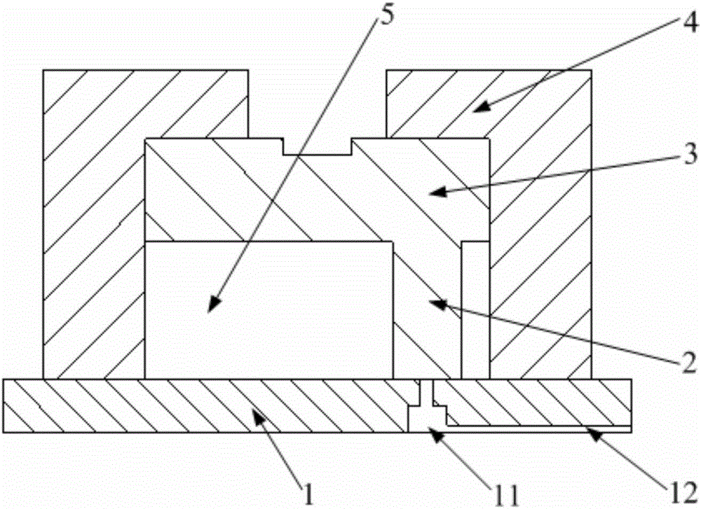
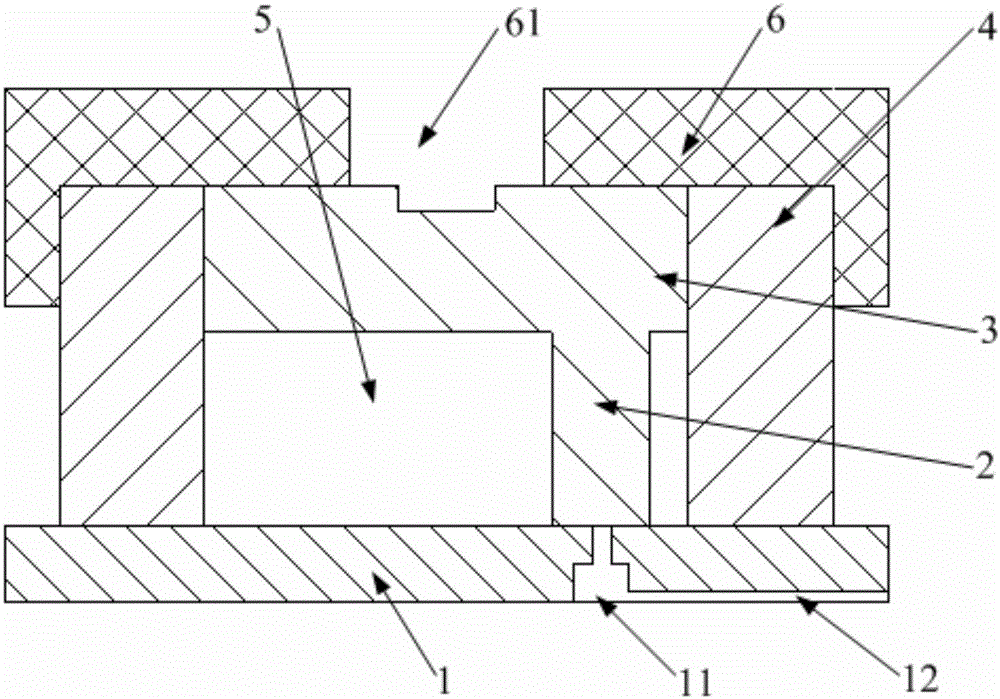
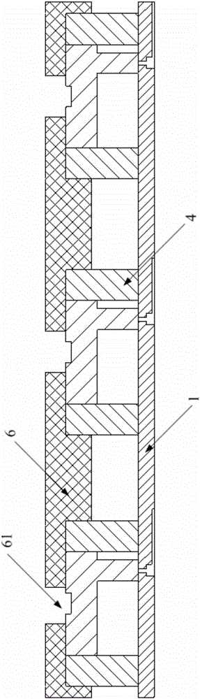
[0047] An embodiment of the present invention provides a microfluidic valve with a stirring function, thereby reducing the number of components installed on a microfluidic chip, thereby facilitating assembly.

[0048] In order to make the purpose, technical solutions and advantages of the embodiments of the present invention clearer, the technical solutions in the embodiments of the present invention will be clearly and completely described below in conjunction with the drawings in the embodiments of the present invention. Obviously, the described embodiments It is a part of embodiments of the present invention, but not all embodiments. Based on the embodiments of the present invention, all other embodiments obtained by persons of ordinary skill in the art without making creative efforts belong to the protection scope of the present invention.

[0049] Please refer to the attached Figure 1-16 , the microfluidic valve provided by the embodiment of the present invention includ...


PUM


Abstract

The invention provides a microfluidic valve and a microfluidic chip. The microfluidic valve comprises a base, a sleeve, a rotor and micro-columns, wherein the base is provided with micropores; the sleeve is arranged on the base; the rotor is rotatablely sheathed on one end of the sleeve away from the base; the rotor, sleeve and base are matched to form a stirring cavity; the micropores can be communicated with the stirring cavity; and the micro-columns are arranged on the rotor and positioned in the stirring cavity, and can seal the micropores. The microfluidic valve provided by the invention can implement the on-off state of the micropores on the base through the rotation of the rotor, and can also implement stirring and mixing on the liquid in the stirring cavity; and therefore, the microfluidic valve has the functions of flow path on-off and fluid stirring, thereby reducing the number of components installed on the microfluidic chip and further being convenient for assembly.

Description

technical field [0001] The present invention relates to the field of microfluidic technology, more specifically, to a microfluidic valve, and also to a microfluidic chip with the microfluidic valve. Background technique [0002] Microfluidic chips precisely control the flow of microfluids in the chip through microvalves. A microvalve, commonly used today, controls fluid flow through a fluid structure at the bottom of the rotor and through holes in the base plate that lead to one or more conduits. By rotating the rotor, the microfluidic control valve connects the pipes under the rotor with the pipes leading to different directions in the substrate to complete the opening and closing of the flow path. [0003] However, the above-mentioned microfluidic valve only completes the on-off function of the flow path through the rotating parts, so it is necessary to use another stirrer to control the fluid movement to realize the fluid mixing, reaction and other operations, which lead...

Claims


Application Information

Patent Timeline
Patent Type & Authority Applications(China)
IPC IPC(8): F16K99/00B81B5/00
CPCF16K99/0011F16K99/0028F16K99/0046F16K2099/0084B01L2300/0867B01L2300/0874F16K99/0013B01L3/502738B01L2300/0816B01L2400/0644B01F25/1051B01F33/3017B01L2200/0647F16K99/0025F16K99/0063
Inventor 王磊周峣王虎林明仙王彤珺白亮黄国亮王东邢婉丽
Owner CAPITALBIO CORP
Why Eureka
Try Eureka