Method for locating leakage position of ore pulp conveying pipe

A leakage location and transmission pipeline technology, applied in the field of transportation control, can solve the problems of enterprise economic loss, environmental pollution, ore slurry leakage, etc.

Inactive Publication Date: 2015-12-09
YUNNAN DAHONGSHAN PIPELINE
View PDF5 Cites 21 Cited by
  • Summary
  • Abstract
  • Description
  • Claims
  • Application Information

AI Technical Summary

Problems solved by technology

Once a leakage accident occurs in the slurry transportation pipeline, if it is not found in time, it will cause major environmental pollution and dangerous accidents. At the same time, if the leakage of the slurry is not taken in time,

Method used


Image

  • Method for locating leakage position of ore pulp conveying pipe

Examples


Embodiment 1

[0027] The method for the leakage position of the slurry conveying pipeline of the present invention, its steps are:

[0028] (1) When the slurry is transported normally, when the slurry pipeline is in normal operation, the outlet pressure, inlet pressure and flow rate of the upstream and downstream pump stations of the slurry pipeline are in a stable state;

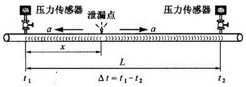
[0029] (2) After a leak occurs at a distance χ from the upstream pumping station of the pipeline, t 1 Time is the time when the negative pressure wave is transmitted to the upstream pumping station of the pipeline, t 2 Time is the time when the negative pressure wave is transmitted to the downstream pumping station of the pipeline. By capturing the time difference between the negative pressure wave reaching the pressure transmitter of the upstream and downstream pumping station of the pipeline, combined with the propagation speed of the negative pressure wave to determine the location of the pipeline leakage, its positio...

Embodiment 2

[0046] A slurry pipeline in China implemented an emergency drill for slurry pipeline leakage in 2014. The inner diameter D of the slurry pipeline is 224.5mm, and the slurry density ρ is 2121kg / m 3, The elastic modulus E of the pipeline material is 2.07*10^11pa, the pipeline wall thickness e is 10mm, the distance L between the upstream and downstream pumping stations is 47 kilometers, and the leakage point is set at a distance of 35.2 kilometers from the upstream pumping station of the pipeline, theoretically calculated by the above method Leakage point, the bulk elastic modulus of the transported pulp is 27*10^7pa measured through experiments, and the negative pressure wave velocity is measured to be about 992m / s through theoretical calculations, and then the negative pressure wave is transmitted to the upstream pump station through the SCADA computer program The time difference Δt with the downstream pumping station is 21.8 seconds. Using the slurry pipeline leakage location f...


PUM

PropertyMeasurementUnit
Densityaaaaaaaaaa
Elastic modulusaaaaaaaaaa
Wall thicknessaaaaaaaaaa

Abstract

The invention provides a method for locating the leakage position of an ore pulp conveying pipe, relates to a conveying control method, in particular to the method for determining the leakage position when the conveying pipe is blocked in the long-distance iron concentrate ore pulp conveying process. According to the method, by the adoption of a negative-pressure wave method, when the iron concentrate pulp pipe generates leakage, concentrate pulp at a leakage point flows away rapidly due to the difference between the internal pressure and the external pressure of the pipe, and pressure drops down; liquid on both sides of the leakage point is supplemented to the leakage point due to the pressure difference; the above processes are sequentially passed to an upstream pump station and a downstream pump station through the concentrate pulp pipe, that is, negative-pressure waves propagating at a certain speed are generated at the leakage point; and the position of the leakage point can be worked out according to the time difference generated when negative-pressure weaves generated at the leakage point are propagated to the upstream pump station and the downstream pump station and the propagation speed of the negative pressure waves in the pipe. The method has the beneficial effects of being less in required devices, low in operation cost, simple in operation and the like and is superior to an existing method for determining the leakage position of the pipe.

Description

technical field [0001] The invention relates to a transportation control method, in particular to a method for determining the leakage position when the transportation management is blocked during the long-distance iron concentrate slurry transportation process. Background technique [0002] Slurry pipelines are more and more widely used in modern society, but with the extension of pipeline operation time, pipeline leakage due to various external forces, such as earthquakes, construction, and landslides, will cause waste of resources and environmental pollution. Leakage location method, timely and accurate report of the specific geographical location of the accident pipeline, can minimize economic losses and environmental pollution. Once a leakage accident occurs in the slurry transportation pipeline, if it is not found in time, it will cause major environmental pollution and dangerous accidents. At the same time, if the leakage of the slurry is not taken in time, it will br...

Claims


Application Information

Patent Timeline
IPC IPC(8): F17D5/02
Inventor 赵永平普光跃张晓南李学鑫
Owner YUNNAN DAHONGSHAN PIPELINE
Why Eureka
Try Eureka