
Self-collimating grating interferometer with high optical subdivision structure

A grating interference and self-collimation technology, applied in the field of grating interferometers, can solve the problems of insufficient use of gratings, high grating design requirements, low optical subdivision multiples, etc. high effect

Active Publication Date: 2017-07-14
SHANGHAI INST OF OPTICS & FINE MECHANICS CHINESE ACAD OF SCI
View PDF12 Cites 0 Cited by
  • Summary
  • Abstract
  • Description
  • Claims
  • Application Information

AI Technical Summary

Problems solved by technology

In order to solve the problem of generally low optical subdivision multiples, the patented high subdivision high-density grating interferometer CN104613865A proposes to use a high subdivision prism so that the measurement beam is reflected by the grating scale multiple times to obtain high-magnification optical subdivision, but the high subdivision prism requires special The processing and process are complicated, and the adjustment of the optical path is difficult. The patent CN104729402A of the high optical subdivision grating interferometer based on the plane mirror proposes the function of directly using the plane mirror instead of the special prism. High, the patented high-resolution grating interferometer based on high-density gratings CN104729411A proposes to use double gratings to achieve high-magnification subdivision effects, which not only simplifies the complex manufacturing process, but also has the same incident angle of the measuring beam incident on the grating scale each time, reducing The requirements of the grating design are met, but because the measuring beam is diffracted by two high-density gratings, the energy loss of the measuring beam increases, which limits the increase in the optical subdivision multiple
Moreover, none of the patents of the above-mentioned high-resolution grating interferometer adopts the Bragg angle incident grating scale of the grating, and does not make full use of the highest characteristics of the grating at this angle.

Method used


Image

  • Self-collimating grating interferometer with high optical subdivision structure
  • Self-collimating grating interferometer with high optical subdivision structure
  • Self-collimating grating interferometer with high optical subdivision structure

Examples


Embodiment 1

[0024] Example 1: A measuring beam

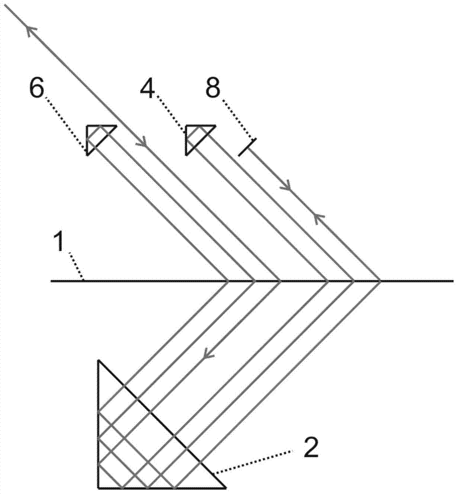
[0025] see figure 1 , figure 1 It is a schematic diagram of Embodiment 1 of the high optical subdivision structure of the self-collimating grating interferometer of the present invention

[0026] A highly optically subdivided structure of a self-collimating grating interferometer with only one measuring beam as figure 1As shown, it is mainly used in the grating interferometer where the measuring beam and the reference beam form interference fringes. It can be seen from the figure that the high optical subdivision structure of the self-collimating grating interferometer of the present invention includes: a grating scale 1 , a first right-angle prism 2 , a second right-angle prism 4 , a third right-angle prism 6 , and a first mirror 8 . After the measurement beam is incident on the grating scale 1 at the m-order Bragg angle for the first time, it is diffracted by the grating scale. Parallel to the incident light incident on the right-angl...

Embodiment 2

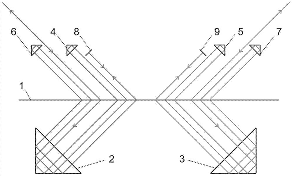
[0028] The highly optically subdivided structure of the self-collimating grating interferometer with two measuring beams is as follows: figure 2 As shown, it is mainly used in a grating interferometer in which two beams of measuring light form interference fringes. The structure includes: a grating scale 1, a first rectangular prism 2, a second rectangular prism 4, a third rectangular prism 6, a fourth rectangular prism 3, a fifth rectangular prism 5, a sixth rectangular prism 7, a first reflector 8, Second reflector 9. Compared with the high optical subdivision structure of the self-collimating grating interferometer when there is only one measuring beam, the fourth right-angle prism 3 , the fifth right-angle prism 5 , the sixth right-angle prism 7 and the second reflection mirror 9 are added. At this time, the fourth right-angle prism, the fifth right-angle prism, the sixth right-angle prism, and the second reflector are respectively placed symmetrically with the first rig...

Embodiment 3

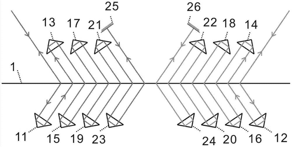
[0030] image 3 It is a schematic diagram of the high optical subdivision structure of another self-collimating grating interferometer with two measuring beams. The first measuring beam is incident on the grating scale 1 at the m-order Bragg angle, and passes through the first right-angle prism 11, the grating scale 1, the second right-angle prism 13, the grating scale 1, the third right-angle prism 15, the grating scale 1, the fourth Right-angle prism 17, grating scale 1, the fifth right-angle prism 19, grating scale 1, the sixth right-angle prism 21, grating scale 1, the seventh right-angle prism 23, grating scale 1, the -m order diffracted light at this moment is vertically incident on the first On a reflector 25, the light beam returns along the original path, and finally coincides with the first initial incident measurement beam, and forms the first outgoing measurement beam in a reverse direction opposite to the first initial incident measurement beam;

[0031] Similar ...


PUM


Abstract

A high optical subdivision structure of an auto-collimation grating interferometer includes a grating scale, a first rectangular prism, a second rectangular prism, a third rectangular prism, a fourth rectangular prism, a fifth rectangular prism, a sixth rectangular prism, a first reflecting mirror, and a second reflecting mirror. The high optical subdivision structure of the auto-collimation grating interferometer enables a measurement light beam of the grating interferometer to be reflected back and forth between the grating scale with high diffraction efficiency and the reflecting mirror, and increases times that the measurement light beam is diffracted by the grating scale by fully utilizing the characteristic that the grating is easy to obtain the high diffraction efficiency at a Bragg angle.

Description

technical field [0001] The invention relates to a grating interferometer, in particular to a high optical subdivision structure of the self-collimating grating interferometer, which can greatly increase the optical subdivision multiple of the grating interferometer. Background technique [0002] There are currently two main types of instruments for micro-nano precision displacement measurement: laser interferometer and grating interferometer. Laser interferometer is based on wavelength and can obtain high resolution, but its application is limited because the wavelength is easily affected by factors such as environment and light source. The grating interferometer just makes up for the shortcomings of the laser interferometer. It uses the grating period as the reference, and the measurement results are basically not affected by the environment and wavelength. It has been widely used in processing machine tools, robots, biomedical and other fields. [0003] Whether it is a la...

Claims


Application Information

Patent Timeline
Patent Type & Authority Patents(China)
IPC IPC(8): G01B9/02
Inventor 卢炎聪周常河韦春龙余俊杰李树斌王津李燕阳李民康
Owner SHANGHAI INST OF OPTICS & FINE MECHANICS CHINESE ACAD OF SCI
Learn More