
Five-axis linkage machine tool rotation shaft geometric error continuous measurement method

A five-axis linkage machine tool and geometric error technology, applied to measuring devices, instruments, optical devices, etc., can solve the problems of limited measurement efficiency and low measurement accuracy

Active Publication Date: 2015-12-09
HUAZHONG UNIV OF SCI & TECH
View PDF4 Cites 55 Cited by
  • Summary
  • Abstract
  • Description
  • Claims
  • Application Information

AI Technical Summary

Problems solved by technology

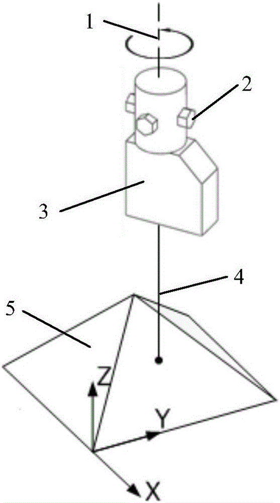
[0004] However, after further research, the above existing technologies still have the following defects or deficiencies: on the one hand, when using a discrete measuring instrument, its measurement accuracy is limited by the distribution density of the sampling points of the rotating shaft, and the measurement accuracy is low; on the other hand, using For continuous measuring instruments, the two ends are usually connected to the main shaft and the worktable respectively, and the error transmission part adopts a static connection method, that is, the shape and appearance of the sensor remain unchanged, but the spatial pose of a rigid body requires at least three non-collinear points Therefore, it is limited by the motion constraints of the static connection of the error conduction part. It needs to install the measuring instrument multiple times to perform the entire measurement process, and the measurement efficiency is greatly limited.

Method used


Image

  • Five-axis linkage machine tool rotation shaft geometric error continuous measurement method
  • Five-axis linkage machine tool rotation shaft geometric error continuous measurement method
  • Five-axis linkage machine tool rotation shaft geometric error continuous measurement method

Examples


Embodiment Construction

[0052] In order to make the object, technical solution and advantages of the present invention clearer, the present invention will be further described in detail below in conjunction with the accompanying drawings and embodiments. It should be understood that the specific embodiments described here are only used to explain the present invention, not to limit the present invention. In addition, the technical features involved in the various embodiments of the present invention described below can be combined with each other as long as they do not constitute a conflict with each other.

[0053] The purpose of the present invention is mainly achieved by the following methods: first select a laser displacement sensor (laserdisplacementsensor, LDS) as a measuring instrument, its characteristics can meet the needs of continuous measurement, and possess the characteristics that the error conduction part is a dynamic connection; then, in order to solve the problem of laser Due to the ...


PUM


Abstract

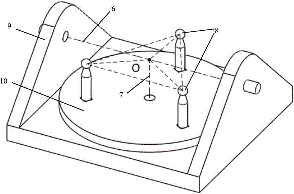
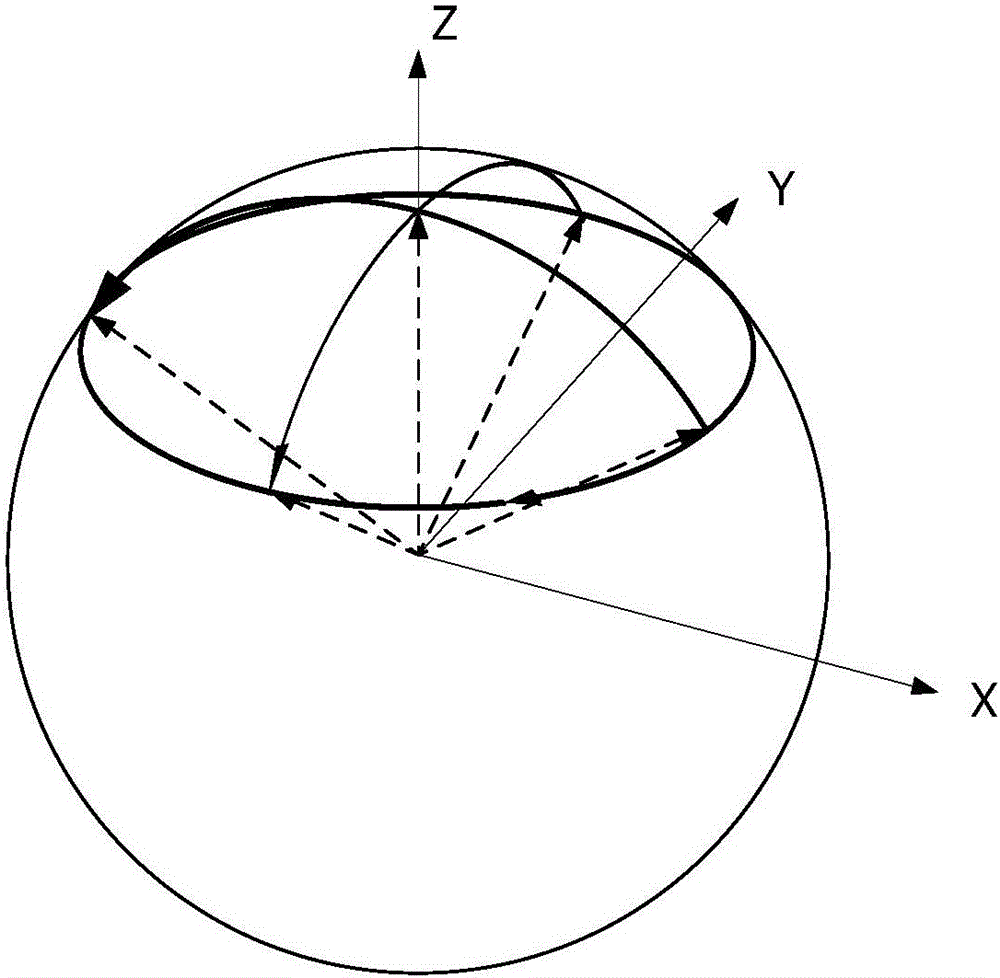
The invention discloses a five-axis linkage machine tool rotation shaft geometric error continuous measurement method. The method comprises the steps that a laser displacement sensor is arranged on a spindle of a five-axis linkage machine tool; three non-collinear calibration balls are arranged on the work bench, and the homogeneous coordinate expression of each calibration ball is set; a swing axis A and a rotary axis C are used as calibration axes; the laser displacement sensor is used to measure the position deviation of the center of each calibration ball in X , Y and Z directions when the swing axis A and the rotary axis C in different corners; and according to the position deviation of the center of each calibration ball and the homogeneous coordinate expression of each calibration ball, geometric errors of the swing axis A and the rotary axis C are calculated. According to the invention, an oblique surface is used to establish the mapping relationship among the position deviation of a rigid body to be measured in X, Y and Z directions; translation in X, Y and Z dimensions is mapped to distance change in a single dimension; one-time chucking and continuous sampling are realized at the same time; and the method has the advantages of high measurement efficiency and high precision.

Description

technical field [0001] The invention belongs to the technical field of geometric error measurement of machine tool rotary shafts, and more specifically relates to a continuous measurement method for geometric errors of five-axis linkage machine tool rotary shafts. Background technique [0002] Five-axis linkage CNC machine tools are currently the only means to solve the processing of complex parts such as impellers, blades, marine propellers, heavy-duty generator rotors, steam turbine rotors, and large diesel engine crankshafts. It has been applied in a certain range in the industrial field. However, in terms of high-speed, high-precision, and intelligent performance, five-axis CNC machine tools have problems such as poor machining accuracy and large errors. The geometric error of the machine tool is one of the main reasons for the machining error of the parts. The geometric error is a systematic error, which has good repeatability and can be greatly reduced through software...

Claims


Application Information

Patent Timeline
IPC IPC(8): G01B11/00
Inventor 周向东唐小琦蒋周翔宋宝熊烁蒋立泉陈天航谢远龙乔文君
Owner HUAZHONG UNIV OF SCI & TECH
Learn More