
Bridge structure damage positioning method based on indicated frequency space-time evolution

A technology for bridge structure and damage location, which is applied to the analysis of solids using sonic/ultrasonic/infrasonic waves. It can solve the problems of low accuracy and reliability, high application cost, damage location, etc., and achieve economical and time cost savings and high data quality. , The effect of low test cost

Active Publication Date: 2015-12-09
江苏德业节能科技发展有限公司
View PDF2 Cites 8 Cited by
  • Summary
  • Abstract
  • Description
  • Claims
  • Application Information

AI Technical Summary

Problems solved by technology

These technologies have their own characteristics, but most of the above-mentioned technologies have defects such as high application cost, low accuracy and reliability, and poor adaptability to complex bridge structures. The time-spatial evolution law of point indicator frequency under different structural damage states in the time domain to realize the technology of damage location

Method used


Image

  • Bridge structure damage positioning method based on indicated frequency space-time evolution

Examples


Embodiment Construction

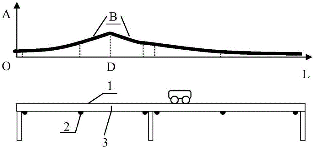
[0022] The present invention will be further described below in conjunction with accompanying drawing and embodiment: figure 1 It is a schematic diagram of the principle of the present invention.

[0023] The bridge structure damage location method based on the temporal and spatial evolution of the index frequency provided by the present invention includes

[0024] a. Data collection is carried out at each spatial position test point of the bridge structure, and the test point forms a spatial grid;

[0025] b. Collect the vibration frequency data of each spatial position test point of the bridge structure;

[0026] c. According to the change law of the vibration frequency of the test points at different spatial locations in the time domain, the damage location of the bridge structure is carried out.

[0027] Wherein, said step c specifically includes

[0028] c1. Based on the vibration frequency data collected at each test point at the initial moment of the bridge structure...


PUM


Abstract

The invention provides a bridge structure damage positioning method based on indicated frequency space-time evolution, wherein the method includes following steps: (a) collecting data at various spatial position test points in a bridge structure, wherein the test points form a spatial lattice; (b) collecting vibration frequency data of various spatial position test points in the bridge structure; c) performing damage positioning to the bridge structure according to the change rules of the vibration frequency of different spatial position test points within a time domain. According to the bridge structure damage positioning method based on the indicated frequency space-time evolution, travelling vehicles, which runs on the bridge structure, are employed as a power excitation source, so that the method is free of manual excitation and is free of interference on normal traffic, thereby saving economic and time cost. The hardware in the method can be changed at any time and is suitable for bridges in different types. By means of bridge structure acceleration response, the method is high in data quality, is stable and reliable, is low in test cost and is suitable for being popularized in large area.

Description

technical field [0001] The invention relates to the field of bridge detection, in particular to a bridge structure damage location method based on the time-space evolution of index frequency. Background technique [0002] With the rapid development of my country's transportation industry, bridge construction, as an important part of transportation, has been widely used in road and railway construction. However, cracks are prone to appear during the construction and use of bridges. The appearance of cracks will not only affect the quality of the project but even lead to the collapse of the bridge. There are many reports about the impact of cracks on the quality of the project and even the collapse of the bridge. Therefore, how to locate and identify damage forms such as bridge structural cracks is of great practical significance. There are many detection methods in the prior art, such as ultrasonic method, optical fiber sensor method, structural mode vibration method, bionic...

Claims


Application Information

Patent Timeline
IPC IPC(8): G01N29/12
Inventor 彭凯李博曹晓川彭撞
Owner 江苏德业节能科技发展有限公司
Learn More