
Adjustable wave energy and hydraulic energy conversion system and control method

A technology of hydraulic energy and conversion system, applied in fluid pressure actuation system components, accumulator devices, fluid pressure actuation devices, etc., can solve the problems of long construction window, high cost, high commissioning cost, etc. Economic and time cost, simple system structure, and the effect of reducing construction difficulty

Pending Publication Date: 2022-07-29
GUANGZHOU INST OF ENERGY CONVERSION - CHINESE ACAD OF SCI
View PDF0 Cites 0 Cited by
  • Summary
  • Abstract
  • Description
  • Claims
  • Application Information

AI Technical Summary

Problems solved by technology

To debug the power generation function of the wave energy power generation device, hundreds of tons of cranes must be used to make the wave-absorbing floating body simulate wave motion for debugging. The cost is very high, and the startup and hoisting of large cranes is very time-consuming and extremely Greatly increased device debugging time
On the sea, after regular maintenance of the wave power generation device, system debugging must also be carried out. At this time, it is even impossible to use a large crane, and it is necessary to use a high-power marine hoist for on-site debugging. Long construction window, which in turn leads to higher commissioning costs

Method used


Image

  • Adjustable wave energy and hydraulic energy conversion system and control method
  • Adjustable wave energy and hydraulic energy conversion system and control method
  • Adjustable wave energy and hydraulic energy conversion system and control method

Examples


Embodiment

[0067] It should be noted that the terms "first", "second" and the like in the description and claims of the present invention and the above drawings are used to distinguish similar objects, and are not necessarily used to describe a specific sequence or sequence. It is to be understood that the data so used may be interchanged under appropriate circumstances such that the embodiments of the invention described herein can be practiced in sequences other than those illustrated or described herein. In addition, the terms "comprising" and "having" and any variations thereof in the embodiments of the present invention are intended to cover non-exclusive inclusion, for example, a process, method, system, product or device comprising a series of steps or units is not necessarily limited to Those steps or elements that are expressly listed may instead include other steps or elements that are not expressly listed or are inherent to the process, method, product or apparatus.

[0068] I...


PUM


Abstract

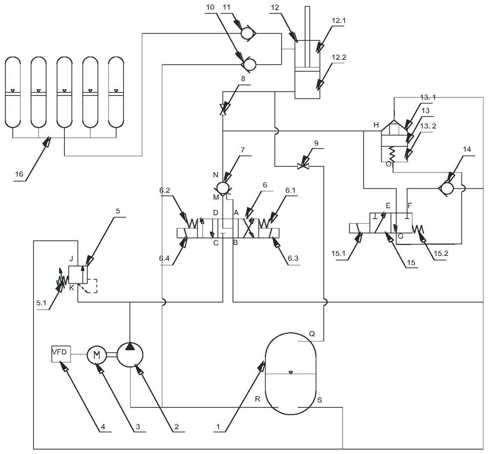
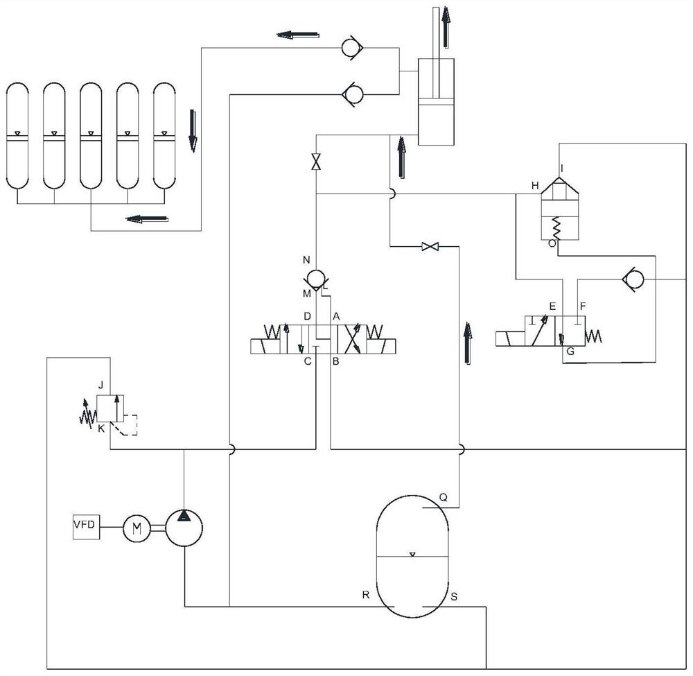
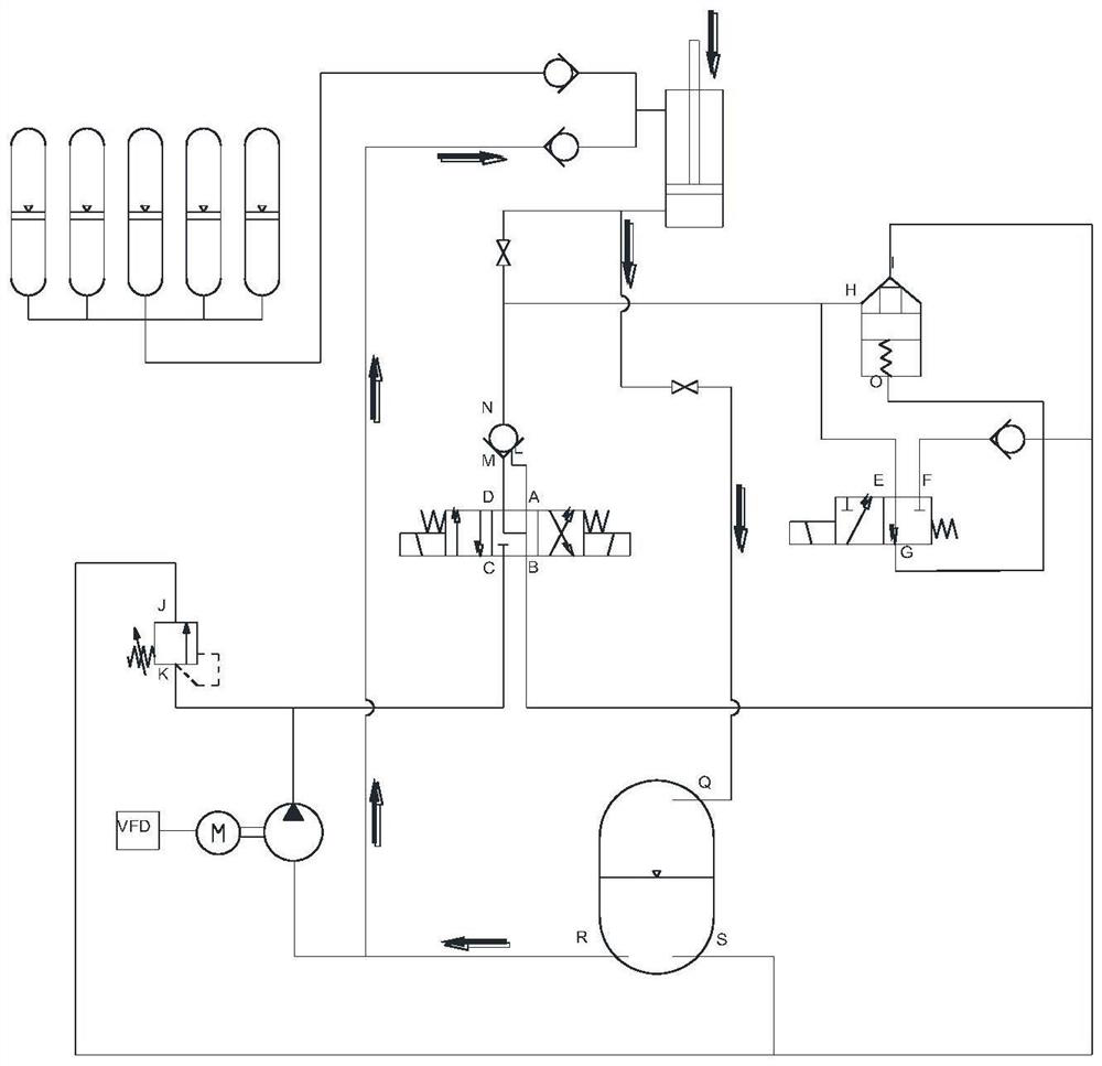
The invention discloses an adjustable hydraulic energy conversion system of a wave energy power generation device, and relates to the control technology of the hydraulic energy conversion system of the wave energy power generation device. The system comprises an oil tank, a hydraulic pump, a motor, a frequency converter, an overflow valve, an adjusting spring, a three-position four-way electromagnetic directional valve, a hydraulic control one-way valve, a ball valve, a one-way valve, a working hydraulic cylinder, a two-way cartridge valve, a two-position three-way electromagnetic directional valve and an electric energy accumulator set. According to the debugging system, on the basis of a hydraulic energy conversion system of the wave energy device, part of electrical and hydraulic equipment is added, a motor and a pump are used as power sources, an electromagnetic directional valve is used for controlling the direction of an oil way, and a power element hydraulic cylinder of the wave energy device is driven to reciprocate up and down. The large wave energy power generation device can be debugged through the energy conversion system of the large wave energy power generation device, the economic and time cost of debugging is greatly reduced, and the construction difficulty during offshore debugging is reduced.

Description

technical field [0001] The invention relates to a control technology for a hydraulic energy conversion system of a wave energy power generation device, in particular to a debuggable wave energy hydraulic energy conversion system and a control method. Background technique [0002] With the rapid development of the social economy and the improvement of people's requirements for the quality of life and the quality of the natural environment, clean and pollution-free renewable energy has gradually become a necessity for energy consumption in various countries. Ocean wave energy is a clean, pollution-free marine renewable energy. With the rapid development of various wave energy technologies, many types of wave energy power generation devices have been tested in real sea conditions of prototype prototypes, and a small number of them have been connected to the grid for commercial operation. Therefore, in the future, there will be more and more large-scale wave power generation de...

Claims


Application Information

Patent Timeline
IPC IPC(8): F15B1/027F15B21/08F15B11/08F15B13/04F15B21/14F03B13/16
CPCF15B1/027F15B1/024F15B21/087F15B11/08F15B13/0401F15B21/14F03B13/16
Inventor 叶寅盛松伟王坤林王振鹏李洪进
Owner GUANGZHOU INST OF ENERGY CONVERSION - CHINESE ACAD OF SCI
Learn More