
Method and device for predicting fatigue life of dissimilar steel joint

A technology of fatigue life prediction and dissimilar steel, applied in the direction of instruments, geometric CAD, calculation, etc., can solve the problems of large randomness, unfavorable fatigue life, large dispersion of high temperature fatigue curve data, etc., to achieve easy operation and control, and save money and time cost effects

Pending Publication Date: 2022-03-11
NORTH CHINA ELECTRICAL POWER RES INST +1
View PDF0 Cites 0 Cited by
  • Summary
  • Abstract
  • Description
  • Claims
  • Application Information

AI Technical Summary

Problems solved by technology

[0003] Usually, fatigue samples of dissimilar steel joints designed with reference to standards are heated in a traditional constant temperature furnace by means of radiation heat transfer. After the entire sample (including the non-gauge length section) reaches a predetermined temperature, a fatigue test is carried out under a constant stress amplitude. Fatigue cracks Cracks may occur in the gauge length section of the sample, that is, the heat-affected zone on the ferrite side or the fusion zone on the austenitic steel side near the fusion line; it may also be caused by the contact position between the mechanical fixture and the sample under high-cycle cyclic loading Large structural stress is generated, which leads to preferential crack initiation and expansion in the base metal area of ​​the ferrite side in the non-gauge length section of the joint sample. Larger, not conducive to effective evaluation of its fatigue life
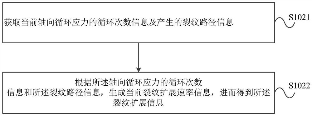
At the same time, it is difficult to study the high temperature fatigue crack growth path and crack growth rate of dissimilar steel joints in depth.

Method used


Image

  • Method and device for predicting fatigue life of dissimilar steel joint
  • Method and device for predicting fatigue life of dissimilar steel joint
  • Method and device for predicting fatigue life of dissimilar steel joint

Examples


Embodiment Construction

[0076] In order to make the purpose, technical solutions and advantages of the embodiments of the present invention more clear, the embodiments of the present invention will be further described in detail below in conjunction with the accompanying drawings. Here, the exemplary embodiments and descriptions of the present invention are used to explain the present invention, but not to limit the present invention. It should be noted that, in the case of no conflict, the embodiments in the present application and the features in the embodiments can be combined arbitrarily with each other.

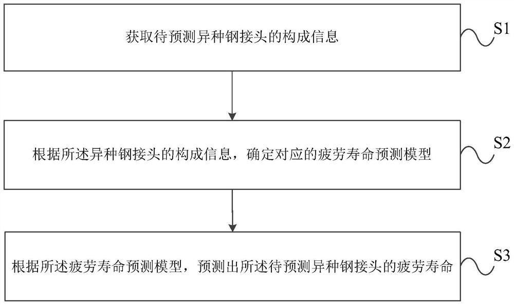
[0077] In a specific example, such as figure 1 As shown, the specific steps to predict the fatigue life of dissimilar steel joints to be predicted include:

[0078] S1: Obtain the composition information of the dissimilar steel joint to be predicted;

[0079] S2: Determine the corresponding fatigue life prediction model according to the composition information of the dissimilar steel joint; ...


PUM


Abstract

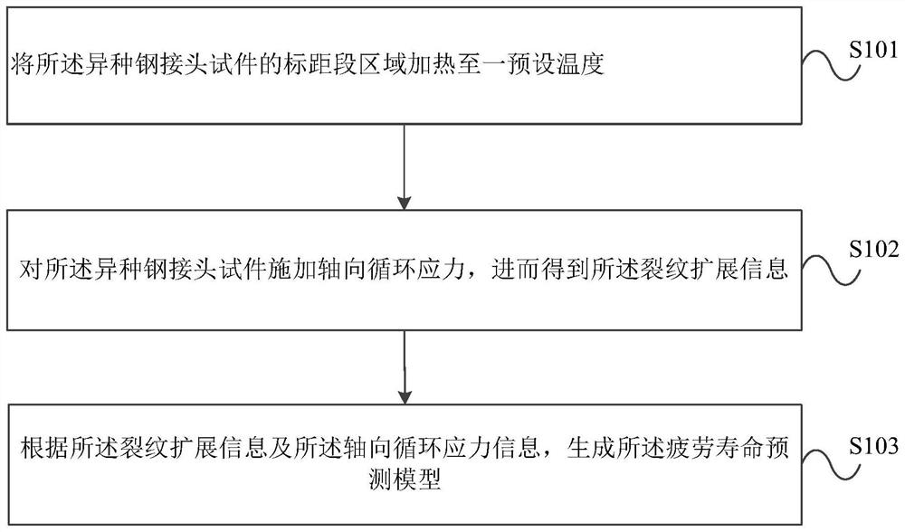
The invention provides a method and a device for predicting the fatigue life of a dissimilar steel joint. The method comprises the following steps: acquiring composition information of a to-be-predicted dissimilar steel joint; determining a corresponding fatigue life prediction model according to the composition information of the dissimilar steel joint; and predicting the fatigue life of the dissimilar steel joint according to the fatigue life prediction model. The device is used for executing the method. According to the method and the device for predicting the fatigue life of the dissimilar steel joint, provided by the invention, real-time observation and measurement of a high-temperature fatigue crack propagation path can be realized, so that the propagation rate of the fatigue crack is further obtained, the method and the device are easy to operate and control, and economic and time costs generated in a test process can be saved.

Description

technical field [0001] The invention relates to the field of welding technology, in particular to a fatigue life prediction method and device for dissimilar steel joints. Background technique [0002] There are a large number of dissimilar steel welded joints (such as T91 / TP347H, T92 / HR3C, T92 / Super304, etc.) composed of ferritic steel and austenitic steel in the heating surface piping system of the boiler of the active ultra-supercritical thermal power unit, almost all of which are made of nickel base alloys as weld filler metals. Production practice shows that the deep peak-shaving operation of thermal power units at a temperature of 500-620 °C is likely to cause serious fatigue damage to the welded joints of the heating surface piping system. Engineering inspections have found that a large number of dissimilar steel joints have early failure after 70,000 to 100,000 hours of service , the service life is much lower than the design life of 200,000 hours. Therefore, there ...

Claims


Application Information

Patent Timeline
IPC IPC(8): G06F30/17G06F119/04G06F119/08G06F119/14
CPCG06F30/17G06F2119/04G06F2119/08G06F2119/14
Inventor 王智春韩哲文王建国彭波宋子博许彬
Owner NORTH CHINA ELECTRICAL POWER RES INST
Learn More