Optical voltage measuring apparatus

A measuring device, optical voltage technology, applied in the direction of measuring devices, measuring electrical variables, measuring current/voltage, etc., can solve the problems of limiting measurement accuracy and response speed, transmittance change error, sensitivity error, etc.

Inactive Publication Date: 2015-12-09
KK TOSHIBA
View PDF6 Cites 1 Cited by
  • Summary
  • Abstract
  • Description
  • Claims
  • Application Information

AI Technical Summary

Problems solved by technology

[0013] However, the optical voltage measuring device 100 is a method of measuring the applied voltage Vm by calculating the degree of modulation of the light quantity, so there is a problem in that it cannot measure the DC voltage essentially.
In addition, sensitivity errors and phase errors will also occur due to environmental changes such as temperature, but this is different from the case of current measuring devices, so they become errors when measuring power and impedance, deteriorating measurement accuracy
In addition, since a voltage divider is required in the measurement, there is also the problem that the measurement ac

Method used


Image

  • Optical voltage measuring apparatus
  • Optical voltage measuring apparatus
  • Optical voltage measuring apparatus

Examples


no. 1 approach

[0067] (Overall structure of the optical voltage measuring device 10)

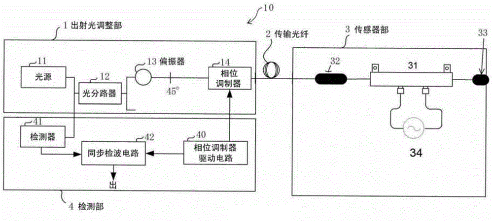
[0068] figure 1 The overall structure of the optical voltage measurement device according to the first embodiment of the present invention is shown in .

[0069] The optical voltage measurement device 10 has: an outgoing light adjustment unit 1, which adjusts the polarization plane of the outgoing light of the light source, and performs phase adjustment of the light; a sensor unit 3, which generates a phase difference proportional to the applied voltage through an electro-optic element 31; a transmission fiber 2 , to connect the outgoing light adjustment unit 1 and the sensor unit 3 ; and the detection unit 4 , to perform wave detection and calculate the voltage.

[0070] (Exit light adjustment unit 1)

[0071] The outgoing light adjustment unit 1 has a light source 11 , an optical splitter (hereinafter also referred to as a “coupler”) 12 , a polarizer 13 , and a phase modulator 14 .

[0072] The light...

no. 2 approach

[0111] Figure 4 The overall structure of the composite optical voltage measuring device according to the second embodiment of the present invention is shown in .

[0112] The composite optical voltage measuring device 20 of the present embodiment is constituted by combining the optical voltage measuring device 10 according to the first embodiment and the reflective (in-line) Sagnac interference type optical current sensor 50, and is combined with a power measuring device 51. The electric power measuring device 51 measures the voltage generated by the optical voltage measuring device 10 and the current generated by the optical current sensor 50 .

[0113] The optical voltage measuring device 10 can not only function as a voltage measuring device alone like the first embodiment, but can also be combined with an ammeter to measure power, electric energy, or reactive power, or to calculate impedance, and use It is used to operate the protection system called remote relay. At th...

no. 3 approach

[0145] (structure)

[0146] Figure 6 The overall structure of the multi-stage optical voltage measuring device according to the third embodiment of the present invention is shown in .

[0147] The multi-stage optical voltage measuring device 30 of the present embodiment has a two-stage structure in which the sensor unit 3 in the optical voltage measuring device 10 of the first embodiment has a first sensor unit 3a and a second sensor unit 3b. The first electro-optical element 37 in the first sensor unit 3 a and the second electro-optical element 38 in the second sensor unit 3 b are connected in series via two Faraday rotators 32 .

[0148] (effect)

[0149] The functions of the outgoing light adjustment part 1 and the transmission fiber 2 are related to figure 1 The optical voltage measuring device 10 is the same, and therefore description thereof is omitted.

[0150] The light emitted from the transmission fiber 2 is rotated by 45° by the Faraday rotator 32 in the first...


PUM


Abstract

An optical voltage measuring apparatus includes at least a light source, an optical branching device, a polarizer, a phase modulator, a transmission fiber, a Faraday rotator that turns the polarized wave of emitted light from the fiber, an electro-optic element that applies refraction index change by a Pockels effect to the turned light, a reflector mirror, and a detector. When the temperature coefficient of the sensitivity of the electro-optic element is positive, incident polarized light orientation of the Faraday rotator to the electro-optic element is set so as to be coaxial with the axis of birefringence that appears by the Pockels effect at the lowest temperature in a service temperature range. When the temperature coefficient of the sensitivity of the electro-optic element is negative, the same setting is made at the highest temperature in the service temperature range.

Description

technical field [0001] Embodiments of the present invention relate to an optical voltage measurement device for measuring voltage of transmission and distribution lines, distribution voltage of electric equipment, and the like. Background technique [0002] Figure 7 A configuration example of a conventional optical voltage measuring device is shown in . [0003] This optical voltage measurement device 100 includes a sensor unit 101 , a light emitting unit 102 , a light receiving unit 103 , and signal processing circuit units (not shown) on the light emitting side and the light receiving side. [0004] The sensor unit 101 includes a polarizer 13 , a quarter-wave plate 35 (hereinafter also referred to as “λ / 4 plate”), an electro-optic element 31 , and an analyzer 52 arranged sequentially on the same optical axis from the light incident side. [0005] In addition, the light emitting unit 102 includes an E / O circuit including a light emitting element such as an LED (Light Emit...

Claims


Application Information

Patent Timeline
IPC IPC(8): G01R19/00
CPCG01R15/242G01R19/32
Inventor 高桥正雄
Owner KK TOSHIBA
Why Eureka
Try Eureka