Eureka AIR delivers breakthrough ideas for toughest innovation challenges, trusted by R&D personnel around the world.

Simulation method and system for particle transport

A technology of particle transport and simulation method, which is applied in the field of particle transport simulation methods and systems, can solve problems such as limited range of use and poor uniformity, and achieve the effects of eliminating uncertainty, reducing time, and improving accuracy

Active Publication Date: 2015-12-09
SHANGHAI UNITED IMAGING HEALTHCARE
View PDF5 Cites 7 Cited by
  • Summary
  • Abstract
  • Description
  • Claims
  • Application Information

AI Technical Summary

Problems solved by technology

However, the quasi-random number technology in the prior art has natural defects, and it is only applicable to regular geometric shapes, especially geometric shapes with symmetry
[0007] It can be seen that the use of pseudo-random or true random numbers in Monte Carlo simulation is not affected by the geometric shape, but its uniformity is poor, and the uncertainty of the simulation is proportional to the -1 / 2 power of the number of particles. The uniformity of random numbers is relatively good, and the uncertainty of the simulation can reach the -1 power of the number of particles. Under the same number of particles, the uncertainty of simulation with pseudo-random numbers is relatively higher than that of pseudo-random numbers or true random numbers. The random number should be reduced a lot, that is, if the same uncertainty requirements are met, the use of quasi-random numbers for simulation can greatly reduce the number of particles used, but quasi-random numbers are only suitable for regular geometric shapes, so the scope of use is very wide. largely restricted

Method used


Image

  • Simulation method and system for particle transport
  • Simulation method and system for particle transport
  • Simulation method and system for particle transport

Examples


Embodiment 1

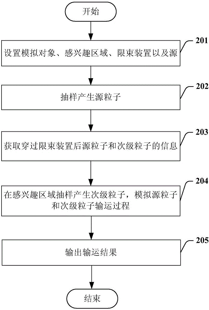
[0052] figure 2 It is a flow chart of the particle transportation method of an embodiment of the present invention. refer to figure 2 As shown, the method of the present embodiment includes the following steps:

[0053] In step 201, set the simulation object, the region of interest, the beam limiting device and the source;

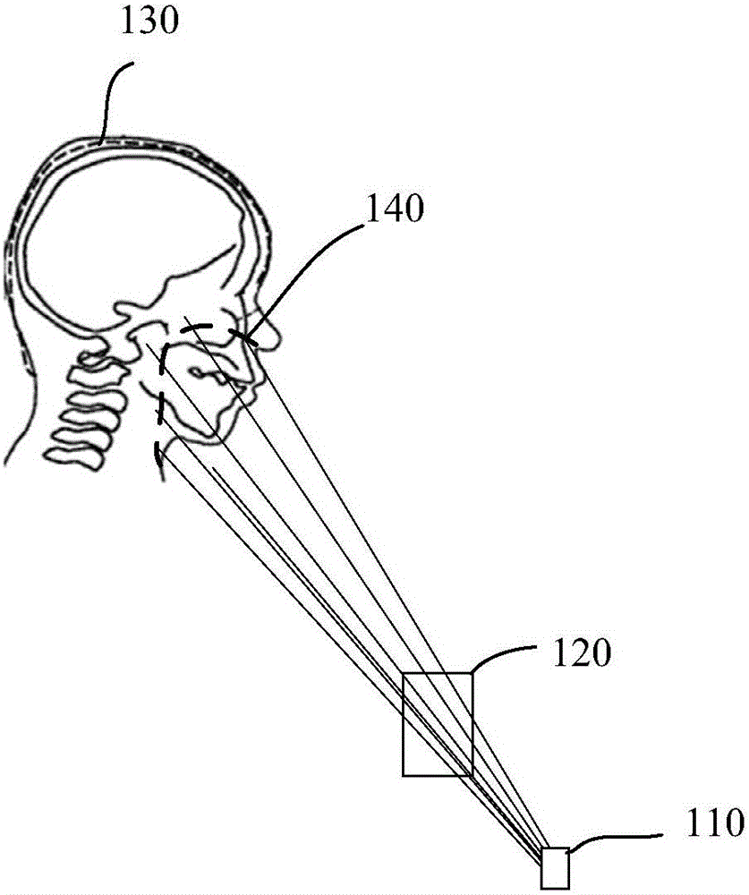
[0054] For example reference figure 1 As shown, a simulated object 130, a region of interest 140, a beam limiting device 120, and a source 110 are set. Specifically, it can be input into the Monte Carlo program in the form of images or text to set the simulated object 130, and set the shape, position and other information of the region of interest 140; for the beam limiting device 120, it is necessary to set the shape and material, wherein the beam limiting device 120 can also include a plurality of beam limiting components, and the beam limiting device 120 can be set by respectively setting the shape and material of each beam limiting component; in ...

Embodiment 2

[0089] The method of particle transportation in this embodiment still refers to figure 2 shown, including the following steps:

[0090] In step 201, set the simulation object, the region of interest, the beam limiting device and the source;

[0091] In step 202, source particles are sampled. The information of the generated source particle includes the particle's weight, direction, position, type, and includes one of energy and velocity. The initial weight of each particle is preset, and these weights can be adjusted later in the process.

[0092] In step 203, the information of the source particle and the secondary particle after passing through the beam limiting device is obtained.

[0093] In step 204, secondary particles are generated by sampling in the region of interest, and the transport process of source particles and secondary particles is simulated.

[0094] In this embodiment, the method of sampling the source particles is different from the method of sampling ...

Embodiment 3

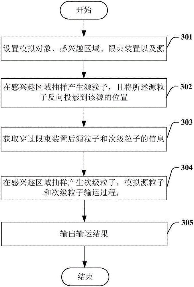
[0108] image 3 It is a flow chart of the particle transportation method of an embodiment of the present invention. refer to image 3 As shown, the method of the present embodiment includes the following steps:

[0109] In step 301, the simulation object, the region of interest, the beam limiting device and the source are set;

[0110] In step 302, source particles are generated by sampling in the region of interest, and the source particles are back-projected to the position of the source. The information of the generated source particle includes the particle's weight, direction, position, type, and includes one of energy and velocity. The initial weight of each particle is preset, and these weights can be adjusted later in the process.

[0111] refer to figure 1 As shown, the source particles can be generated by sampling in the region of interest, and the source particles can be back-projected to the position of the source 110 .

[0112] In step 303, the information of...


PUM


Abstract

The invention provides a simulation method and system for particle transport. The simulation method for particle transport comprises the following steps that a simulation object, an interest area, a beam restriction device and a source are arranged; source particles are generated by sampling, and information of the generated source particles comprises the weight, direction, position and type of the source particles and comprises one of the energy and the speed of the source particles; information of the source particles and secondary particles penetrating through the beam restriction device is acquired; the secondary particles are generated by performing sampling in the interest area, and the transport process of the source particles and the secondary particles is simulated; a transport result is output, wherein a super uniform random number sampling method is adopted as the method for generating the source particles by sampling and generating the secondary particles by sampling in the interest area, and the super uniform random number is a sequence obtained through the steps that an interval is equally divided to obtain multiple numbers and the order of the numbers is disrupted.

Description

technical field [0001] The invention relates to the field of particle transport simulation, in particular to a particle transport simulation method and system. Background technique [0002] In the field of particle transport simulation, Monte Carlo (MC, also known as stochastic simulation method) is widely used to simulate the particle transport process. There are two main factors to consider in the simulation process: the simulation accuracy and the time it takes. Therefore, improving the accuracy of Monte Carlo simulation and reducing the simulation time are the long-term goals of particle transport simulation. [0003] The first way to improve the simulation accuracy is to increase the number of simulated particles, but the accuracy improvement brought by the increase in the number of particles is not obvious, but the computational resources consumed are unbearable. Most of the time spent in the Monte Carlo simulation process comes from the time spent in the random samp...

Claims


Application Information

Patent Timeline
IPC IPC(8): G06F17/50
Inventor 李贵张鹏程韩卫
Owner SHANGHAI UNITED IMAGING HEALTHCARE
Why Eureka
Eureka Blog
Learn More