Work-piece crack detection method based on an RFID (Radio Frequency Identification Device)

A crack detection and workpiece technology, which is applied in the field of RFID-based workpiece crack detection, can solve problems such as easy blind spots, troublesome workpiece detection, and high labor intensity, and achieve the effect of small size, flexible shape and easy operation of the equipment

Inactive Publication Date: 2015-12-09
ZHUZHOU CSR TIMES ELECTRIC CO LTD
View PDF4 Cites 9 Cited by
  • Summary
  • Abstract
  • Description
  • Claims
  • Application Information

AI Technical Summary

Problems solved by technology

Since the workpiece is generally installed on industrial equipment, the crack detection of the workpiece is generally very troublesome. At present, it mainly relies on manual visual inspection, which has the disadvantages of high labor intensity and easy blind spots.

Method used


Image

  • Work-piece crack detection method based on an RFID (Radio Frequency Identification Device)
  • Work-piece crack detection method based on an RFID (Radio Frequency Identification Device)
  • Work-piece crack detection method based on an RFID (Radio Frequency Identification Device)

Examples


Embodiment 1

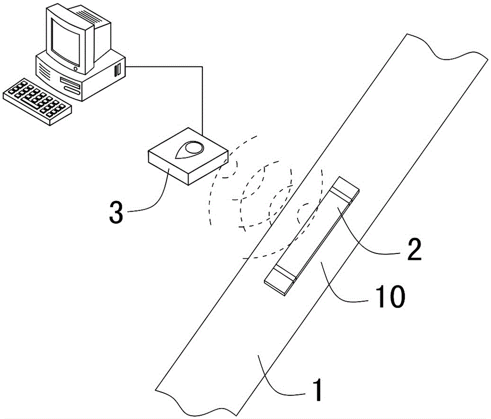
[0035] Hereinafter, taking the crack detection of the to-be-detected crack position 10 on the detected workpiece 1 having a rod-shaped structure as an example, the RFID-based workpiece crack detection method of the present invention will be further described in detail.

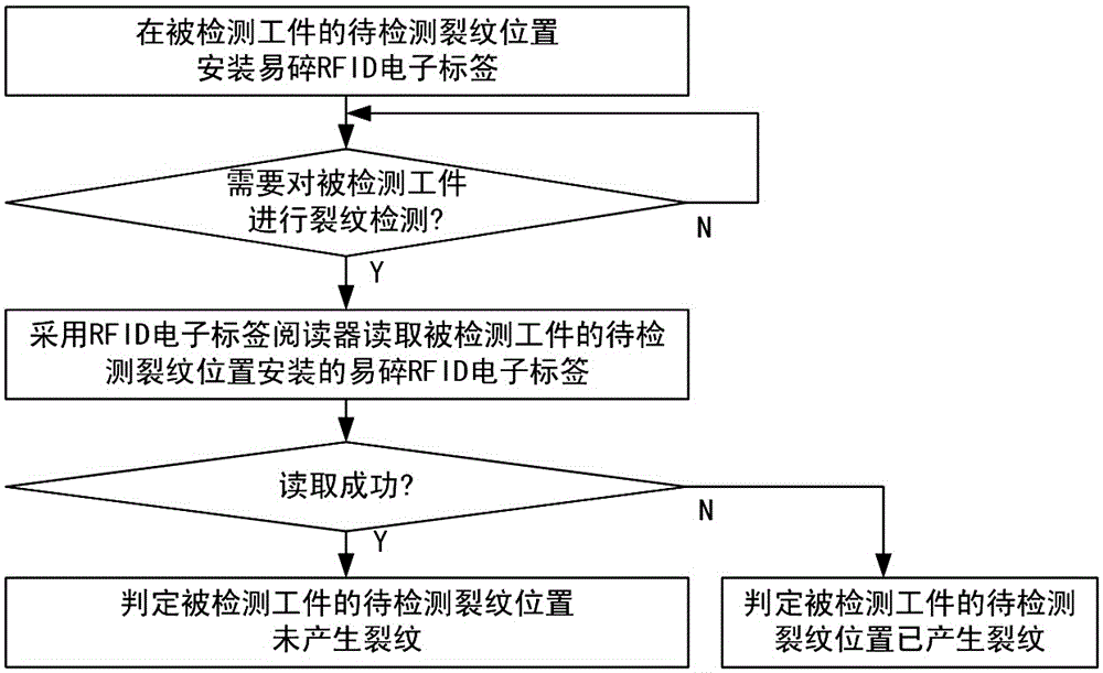
[0036] Such as figure 1 As shown, the steps of the RFID-based workpiece crack detection method in this embodiment include:

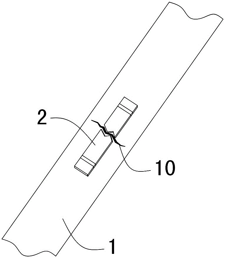
[0037] 1) Pre-install the fragile RFID electronic tag 2 at the crack position 10 to be detected on the workpiece 1 to be detected, so that the fragile RFID electronic tag 2 is respectively connected and fixed to both sides of the crack position 10 to be detected on the workpiece 1; see figure 2 One end of the fragile RFID electronic tag 2 is connected and fixed to one side of the crack position 10 to be detected on the workpiece 1 to be detected, and the other end is connected and fixed to the other side of the crack position 10 to be detected on the workpiece 1 to be detected.

[0038...

Embodiment 2

[0049] This embodiment is basically the same as the first embodiment, and the difference is that the structure of the workpiece 1 to be detected is different, and the position of the crack position 10 to be detected is different. The rod-shaped structure of the workpiece 1 to be detected in the first embodiment is somewhere on the rod where the crack position 10 is to be detected; Figure 4 and Figure 5 As shown, the workpiece 1 to be detected in this embodiment is a connecting rod assembly, and the crack position 10 to be detected is the root of the connecting ring at one end of the connecting rod assembly, and the root of the connecting ring is the position where cracks are most likely to occur in the connecting rod assembly. The RFID-based workpiece crack detection method of the present invention can quickly and conveniently detect whether cracks have occurred at the crack position 10 of the connecting rod assembly to ensure that the structure of the connecting rod assembl...


PUM


Abstract

The invention discloses a work-piece crack detection method based on an RFID (Radio Frequency Identification Device). The work-piece crack detection method comprises the following steps: installing a fragile RFID electronic tag at a crack position to be detected of a detected work-piece in advance, so that the fragile RFID electronic tag is respectively connected and fixed with two sides of the crack position to be detected on the detected work-piece; and reading the installed fragile RFID electronic tag at the crack position to be detected on the detected work-piece by adopting an RFID electronic tag reader in need of detecting the crack of the detected work-piece, if reading successfully, judging that the crack is not generated at the crack position to be detected on the detected work-piece, and if not, judging that the crack is generated at the crack position to be detected. According to the invention, a work-piece is unnecessary to take down from equipment; and the work-piece crack detection method has the advantages of being rapid in identification speed, wide in identification range, easy to operate and control, simple, practical, small in equipment volume, flexible in shape, convenient in data format updating, good in safety and wide in application range and is capable of realizing penetrability and non-barrier detection.

Description

technical field [0001] The invention relates to a crack detection technology of a workpiece, in particular to an RFID-based crack detection method for a workpiece. Background technique [0002] In industrial equipment, the reliability of some key workpieces is directly related to the operation reliability of the entire equipment, so it is very important for the crack detection of workpieces. For example, fatigue fracture detection of key parts of automobile frame, crack detection of locomotive wheels, fracture detection of building steel components and other applications. Since the workpiece is generally installed on industrial equipment, it is generally very troublesome to detect cracks on the workpiece. At present, it mainly relies on manual visual inspection, which has the disadvantages of high labor intensity and easy blind spots. [0003] Radio Frequency Identification (RFID), also known as radio frequency identification, is a wireless communication technology that can...

Claims


Application Information

Patent Timeline
Patent Type & Authority Applications(China)
IPC IPC(8): G06K17/00
Inventor 王俊平施蔚加贺文童磊张小珍赵科龙沈云波凌志辉阳帆尤勇王俊峰李萍言珊胡秋平
Owner ZHUZHOU CSR TIMES ELECTRIC CO LTD
Why Eureka
Try Eureka