
Conductor for dry-type transformer and its manufacturing process and manufacturing equipment
A dry-type transformer and wire technology, applied in the direction of transformer/inductor coil/winding/connection, cable/conductor manufacturing, conductor, etc., can solve the problems of volatilization of insulating paint solvent, generation of air bubbles, affecting the service life of transformer, etc., to simplify The effect of manufacturing process, lateral thickness reduction, and overall cost saving
- Summary
- Abstract
- Description
- Claims
- Application Information
AI Technical Summary
Problems solved by technology
Method used
Image

Examples
Embodiment Construction
[0029] Combine below Figure 4 , Figure 5 , Image 6 , attached Figure 7 , attached Figure 8 and attached Figure 9 The present invention is described in further detail.
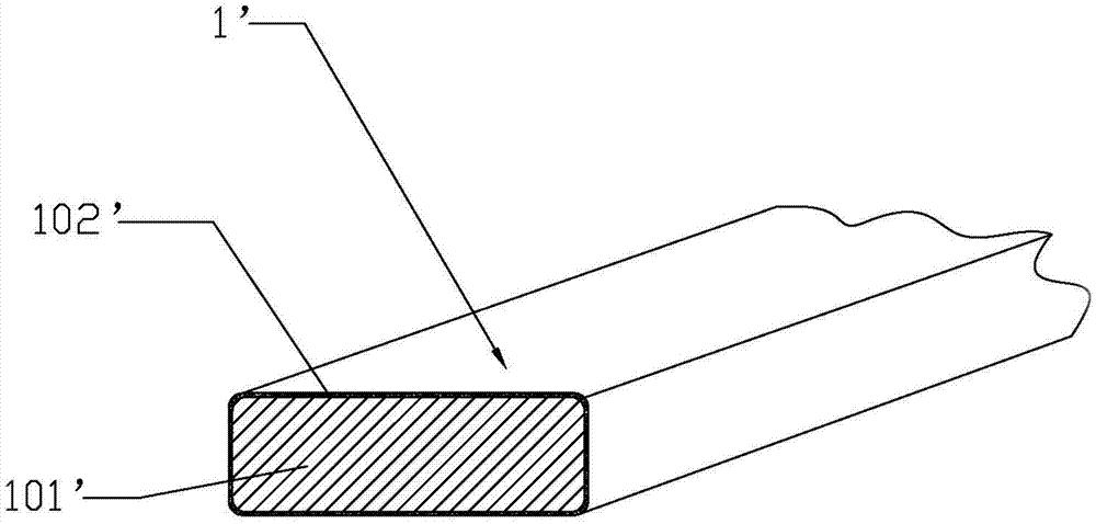
[0030] as attached Image 6 As shown, the present invention is a wire for a dry-type transformer, which includes a conductive body 101, and it also includes a glass fiber tape 102 wound and fixed on the outer peripheral surface of the conductive body 101 in a spiral form; the upper phase of the conductive body 101 is Adjacent glass fiber strips 102 are distributed at intervals, wherein the spacing between adjacent glass fiber strips 102 is 2-3mm; Figure 4 In the above, we mark the wire composed of the conductive body 101 and the glass fiber ribbon 102 spirally distributed on the conductive body 101 with the reference numeral 1, wherein the glass fiber ribbon 102 is wound and fixed on the conductive body 101 in a helical form, and the same The distance between the adjacent glass fiber strips 102 is...
PUM
 Abstract
Description
Claims
Application Information