
Focusing device of large-beam electron beam shooting micro-beam spot X-ray source and application method of focusing device

An electron beam and X-ray technology, applied in the field of three-dimensional non-destructive microscopic observation, can solve the problems of slow beam switching process, weak X-ray intensity, and difficulty in reproducing sample growth and changes, so as to improve work efficiency and simplify complex adjustments , Reduce the effect of adjustment complexity

Active Publication Date: 2015-12-09
BEIHANG UNIV +1
View PDF8 Cites 5 Cited by
  • Summary
  • Abstract
  • Description
  • Claims
  • Application Information

AI Technical Summary

Problems solved by technology

[0005] The focusing system of "fine-focus X-ray source" is mostly modified or referred to the magnetic lens used in electron microscopes. When the electron beam spot on the target surface is small, the beam current is small, and the X-ray intensity generated is weak, so it is difficult to obtain high-resolution images. picture
In addition, the parameters of the condenser lens and the objective lens affect each other, the beam switching process is relatively slow, and it is difficult to reproduce the dynamic process of the growth and change of the sample

Method used


Image

  • Focusing device of large-beam electron beam shooting micro-beam spot X-ray source and application method of focusing device
  • Focusing device of large-beam electron beam shooting micro-beam spot X-ray source and application method of focusing device
  • Focusing device of large-beam electron beam shooting micro-beam spot X-ray source and application method of focusing device

Examples


Embodiment Construction

[0059] The present invention will be further described in detail with reference to the accompanying drawings and embodiments.

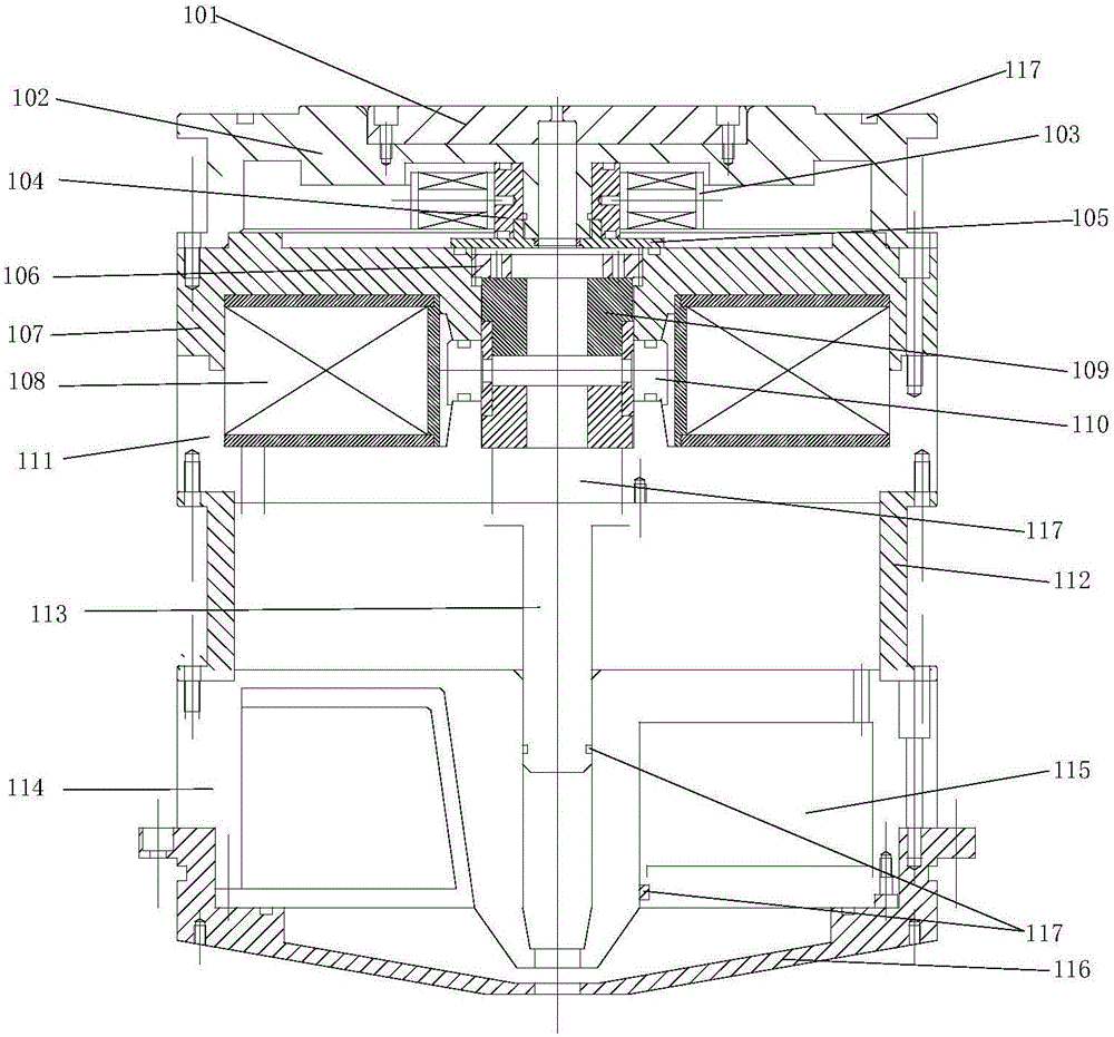
[0060] A focusing system device for a large-current electron beam targeting a micro-beam spot X-ray source, including an anode module, a centering coil module, a condenser lens module, an objective lens module, a movable diaphragm, a transition section module and an electron beam channel.

[0061] The focus system device is a cylindrical structure as a whole, such as figure 1 As shown, the electron beam channel 113 is located on the central axis of the focusing system device, and adopts a hollow magnetic permeable tube that disperses electrons, passing through the anode module, the centering coil module, the condenser lens module, the transition section module, and the objective lens module in sequence from top to bottom. reach the target plane; at the same time, two sealing rings 117 are set inside the electron beam channel 113 .

[0062] The anode ...


PUM


Abstract

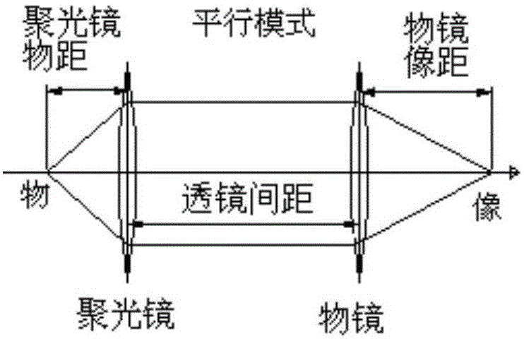
The invention discloses a focusing device of a large-beam electron beam shooting micro-beam spot X-ray source and an application method of the focusing device. The focusing device comprises a condenser module, a transition section module, a movable diaphragm module, an objective lens module and an electronic beam channel, wherein an electronic beam emitted from an electronic gun passes through the condenser module, and forms a parallel beam under the action of a magnetic field formed by the condenser module; after the transition section module is passed, an incident angle of a target surface electron beam is adjusted by moving a movable diaphragm and selecting a proper light-pass hole in the movable diaphragm; and the beam flow size and the beam spot size on the target plane are changed. The application of the focusing device comprises the following steps: (1) setting initial conditions and performance indexes; (2) setting parameters of the objective lens module; (3) setting the parameters of the condenser module, and realizing a parallel work mode; and (4) realizing rapid switching between electron beam flows and forming large-beam micro-beam spots on the target surface. The focusing device has the advantages that by the parallel mode, no electron beam intersection point exists; and the coulomb force effect between electrons is reduced.

Description

technical field [0001] The invention belongs to the technical field of three-dimensional non-destructive microscopic observation, and in particular relates to a focusing device and a using method of a large-beam electron beam targeting a micro-beam spot X-ray source. Background technique [0002] X-ray not only has short wavelength, high resolution, but also has a large penetration depth. Its non-destructive imaging capability provides technical means for scientific research observation and industrial inspection. The X-ray three-dimensional imaging microscope that uses X-rays as a detection method uses perspective projection imaging at different angles, combined with computer three-dimensional digital imaging construction technology, to clearly, accurately and intuitively display the internal structural characteristics and material density of the detected object in the form of images , the presence or absence of defects, the location and size of defects, and other informatio...

Claims


Application Information

Patent Timeline
Patent Type & Authority Applications(China)
IPC IPC(8): H01J35/14
Inventor 李文萍刘俊标韩立霍荣岭初明璋殷伯华薛虹陈志琪
Owner BEIHANG UNIV
Learn More