
Magnetic field injection molding equipment used for magnetic motor rotor

An injection molding, motor rotor technology, applied in magnetic objects, manufacturing stator/rotor bodies, circuits, etc., can solve problems such as reduced production efficiency, inability to fall, and poor mold fit, to improve injection quality, speed up The effect of rotor discharge and production cost saving

Active Publication Date: 2015-12-09
郎溪亚博磁电科技有限公司
View PDF7 Cites 2 Cited by
  • Summary
  • Abstract
  • Description
  • Claims
  • Application Information

AI Technical Summary

Problems solved by technology

[0002] In some cases, the motor rotor needs to be produced into a rotor with high-strength magnetism, which can better increase the speed of the rotor, etc., but currently there is no better magnetic field injection molding machine in the production of magnetic motor rotors. The motor rotor is produced, and after the production, it is magnetized in the radial direction to achieve the purpose of the magnetic motor rotor. This production method is relatively complicated, which greatly increases the production cost and production time of the magnetic motor rotor, and reduces the production efficiency. Or it is to use magnetic materials to directly produce magnetic motor rotors. Although the motor rotors produced by this production method have high magnetic properties, they are all produced with magnetic materials. Since the price of magnetic materials is slightly higher, this method is adopted. The higher production cost is not conducive to improving the economic benefits of the enterprise, and is not conducive to saving resources; moreover, injection molding requires molds, but there are still some shortcomings in the use of the molds set for the magnetic rotor: First, the die-casting of the molds Due to its small volume and light weight, the injection-molded rotor on the surface and the molding surface will be magnetic during the die-casting process. Therefore, after the die-casting is completed, the rotor cannot be dropped quickly due to the magnetism of the molding surface. If it goes down, some rotors will not fall down and will be sandwiched between the two molds during the next die-casting molding, causing damage to the rotor and affecting the normal use of the mold; secondly, the two molds do not have a good positioning device when they are combined for die-casting , resulting in misalignment when the two molds are combined, causing the two molds to not fit tightly and affecting the injection molding quality

Method used


Image

  • Magnetic field injection molding equipment used for magnetic motor rotor
  • Magnetic field injection molding equipment used for magnetic motor rotor
  • Magnetic field injection molding equipment used for magnetic motor rotor

Examples


Embodiment Construction

[0021] In order to enable those skilled in the art to better understand the technical solution of the present invention, the technical solution of the present invention will be further described below in conjunction with the accompanying drawings and embodiments.

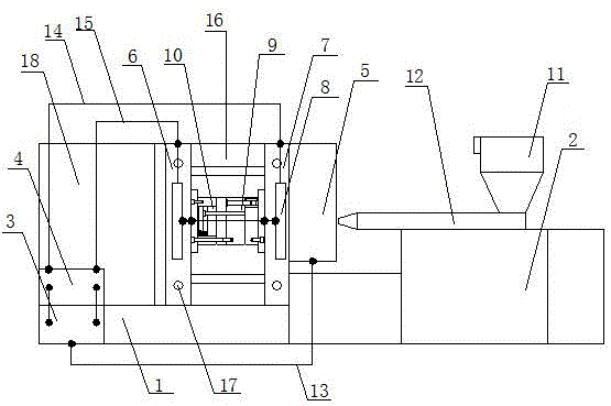
[0022] Refer to attached figure 1 The shown magnetic field injection molding equipment for a magnetic motor rotor includes a magnetic field generating device 1 and an injection molding device 2. The injection molding device 2 includes an injection molding body 18, a hopper 11 and an injection nozzle 12. The front end of the magnetic field generating device 1 is The main controller 5 is arranged on the side, and the magnetic field generating device 1 is arranged at the bottom position of the rear end of the injection molding device 2, and the intelligent charging and demagnetizing controller 3 is arranged at the lower end of the magnetic field generating device 1, and the intelligent charging and demagnetizing control...


PUM


Abstract

The invention discloses magnetic field injection molding equipment used for a magnetic motor rotor. The magnetic field injection molding equipment comprises a magnetic field generation device and an injection molding device. One of the improvements is that an intelligent magnetization and demagnetization controller is arranged at the lower end of the magnetic field generation device. Magnetic field distribution is performed in the internal part of moulds via the intelligent magnetization and demagnetization controller. A mould cavity is arranged at the front end of the upper part of the magnetic field generation device. An injection-molded moving mould and a static mould are arranged in the mould cavity. A magnetic field is piped into the internal part of the moving mould and the static mould. The integrally injection-molded motor rotor is enabled to possess magnetism directly by magnetizing the surface of the rotor in the process of pressure casting molding of the rotor via the magnetic field. According to the magnetic field injection molding machine, the magnetic field and injection molding are integrally arranged so that cost can be saved, resources can be saved, working efficiency and economic benefit can be enhanced and production complexity is reduced. The moulds are simple in structure and high in magnetism, the molded magnetic rotor is convenient in falling without influencing normal use of the moulds, formation of the finished product is fast without clamping or damage phenomenon and yield rate is high.

Description

technical field [0001] The invention relates to a magnetic field injection molding equipment for a magnetic motor rotor. Background technique [0002] In some cases, the motor rotor needs to be produced into a rotor with high-strength magnetism, which can better increase the speed of the rotor, etc., but currently there is no better magnetic field injection molding machine in the production of magnetic motor rotors. The motor rotor is produced, and after the production, it is magnetized in the radial direction to achieve the purpose of the magnetic motor rotor. This production method is relatively complicated, which greatly increases the production cost and production time of the magnetic motor rotor, and reduces the production efficiency. Or it is to use magnetic materials to directly produce magnetic motor rotors. Although the motor rotors produced by this production method have high magnetic properties, they are all produced with magnetic materials. Since the price of mag...

Claims


Application Information

Patent Timeline
IPC IPC(8): H02K15/03H01F13/00B29C45/00B29C45/26
Inventor 吴博
Owner 郎溪亚博磁电科技有限公司
Features
  • Generate Ideas
  • Intellectual Property
  • Life Sciences
  • Materials
  • Tech Scout
  • Unparalleled Data Quality
  • Higher Quality Content
  • 60% Fewer Hallucinations
Learn More