
Permanent magnet screw rod device and splicing method thereof

A technology of permanent magnets and screw rods, which is applied in the direction of electrical components, generators/motors, etc., and can solve problems such as manufacturing difficulties and processing

Active Publication Date: 2015-12-09
SHANGHAI MARITIME UNIVERSITY
View PDF6 Cites 10 Cited by
  • Summary
  • Abstract
  • Description
  • Claims
  • Application Information

AI Technical Summary

Problems solved by technology

The splicing method for the permanent magnet screw device provided by the present invention uses a wire cutting method to perform two different cuts on the traditional semicircular permanent magnet to form a helical permanent magnet; The difficulty in processing and manufacturing linear permanent magnets has promoted the application and development of permanent magnet screw devices

Method used


Image

  • Permanent magnet screw rod device and splicing method thereof
  • Permanent magnet screw rod device and splicing method thereof
  • Permanent magnet screw rod device and splicing method thereof

Examples


Embodiment 1

[0075] Step S1 includes:

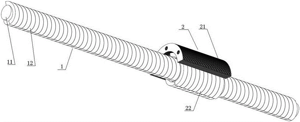
[0076] S1.1A, use the wire cutting method to cut each N-pole semi-annular mover permanent magnet and each S-pole semi-annular mover permanent magnet of the permanent magnet screw shaft 1, so that each N-pole semi-annular mover The permanent magnets and each S-pole semi-annular mover permanent magnet are oblique tile-shaped, and the side surfaces of each N-pole semi-annular mover permanent magnet and each S-pole semi-annular mover permanent magnet are parallelogram-shaped.

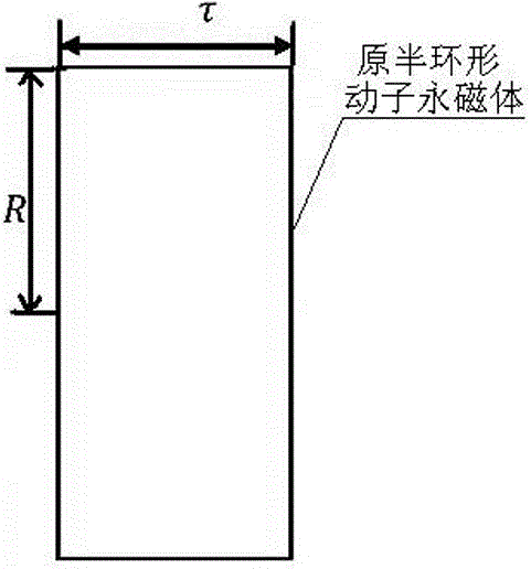
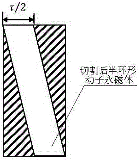
[0077] Such as Figure 2a As shown, the radius of the original N-pole semi-annular mover permanent magnet 12 or the S-pole semi-annular mover permanent magnet is R, and the cross-sectional width is τ. cut out as Figure 2b The shaded part shown makes the remaining part form a slanted shoe shape, that is, form the required 180° helical permanent magnet. Such as Figure 2b As shown, the cross-section of the N-pole semi-annular mover permanent magnet or the S-pole semi-annular mo...

Embodiment 2

[0096] Step S1 includes:

[0097] S1.1B, will be as Figure 2a , Figure 3a Each N-pole half-ring mover permanent magnet and each S-pole half-ring mover permanent magnet of the permanent magnet screw shaft 1 shown rotates along the axis direction angle, such as Figure 4 As shown, the top and bottom of the N-pole semi-annular mover permanent magnet and the top and bottom of the S-pole semi-annular mover permanent magnet are cut by wire cutting method, so that the N-pole semi-annular mover permanent magnet 1. The side of the S-pole semi-annular mover permanent magnet forms a parallelogram; the top and bottom of the N-pole semi-annular mover permanent magnet are all parallel to the axis, and the top and bottom of the S-pole semi-annular mover permanent magnet are all parallel to the axis. parallel. Thereby forming the required 180° helical N pole semi-annular mover permanent magnet and S pole semi-annular mover permanent magnet.

[0098] Among them, the size of each N-pole...


PUM


Abstract

The invention discloses a permanent magnet screw rod device and a splicing method thereof. A permanent magnet screw rod shaft and a permanent magnet rotor assembly are arranged to form the permanent magnet screw rod device. According to the permanent magnet screw rod device provided by the invention, electromagnetic coupling between magnetic poles of the permanent magnet can be adopted to replace mechanical coupling in the prior art, and thus the screw rod device has the advantages of no mechanical wear, overload protection, no mechanical locking and the like. According to the splicing method for the permanent magnet screw rod device provided by the invention, a line cutting processing method is adopted to carry out two kinds of different cutting on the traditional semi-circular ring permanent magnet, and thus a spiral-shaped permanent magnet is formed; and the problems that the spiral-shaped permanent magnet in the prior art is difficult to process and make can be solved, and applications and development of the permanent magnet screw rod device are promoted.

Description

technical field [0001] The invention relates to a high-efficiency linear / rotation conversion device, in particular to a permanent magnet screw device and an assembly method thereof. Background technique [0002] In the prior art, mechanical structures are generally used to achieve efficient linear / rotary conversion; however, mechanical coupling often causes problems such as mechanical friction and wear, overload protection, and mechanical lockup. After the permanent magnet itself is affected by the external magnetic field, due to its high coercive force, the magnetic field is not easy to disappear after the external magnetic field disappears, and it can stably provide a magnetic field to the external space. Through the principle of magnetic force between permanent magnets, power machinery without environmental pollution can be produced. However, in the current design and manufacture of permanent magnet screw rods, it is very difficult to process and manufacture the permanen...

Claims


Application Information

Patent Timeline
Patent Type & Authority Applications(China)
IPC IPC(8): H02N11/00
CPCH02N11/00
Inventor 吴卫民夏永明陆凯元
Owner SHANGHAI MARITIME UNIVERSITY
Features
  • Generate Ideas
  • Intellectual Property
  • Life Sciences
  • Materials
  • Tech Scout
  • Unparalleled Data Quality
  • Higher Quality Content
  • 60% Fewer Hallucinations
Learn More