
Rolling body guide element, particularly for a large tapered roller bearing

A technology for guiding elements and rolling bearings, applied in bearing elements, rolling contact bearings, engine elements, etc., can solve the problems of high friction loss of bearings, difficult lubrication conditions, deviation of expected life, etc. Effect

Inactive Publication Date: 2015-12-09
SCHAEFFLER TECH AG & CO KG
View PDF8 Cites 0 Cited by
  • Summary
  • Abstract
  • Description
  • Claims
  • Application Information

AI Technical Summary

Problems solved by technology

However, full roller bearings without cages suffer from high friction losses and are overall heavy
Furthermore, there are difficult lubrication conditions in these bearings and thus cause large deviations in predictable life expectancy

Method used


Image

  • Rolling body guide element, particularly for a large tapered roller bearing
  • Rolling body guide element, particularly for a large tapered roller bearing
  • Rolling body guide element, particularly for a large tapered roller bearing

Examples


Embodiment Construction

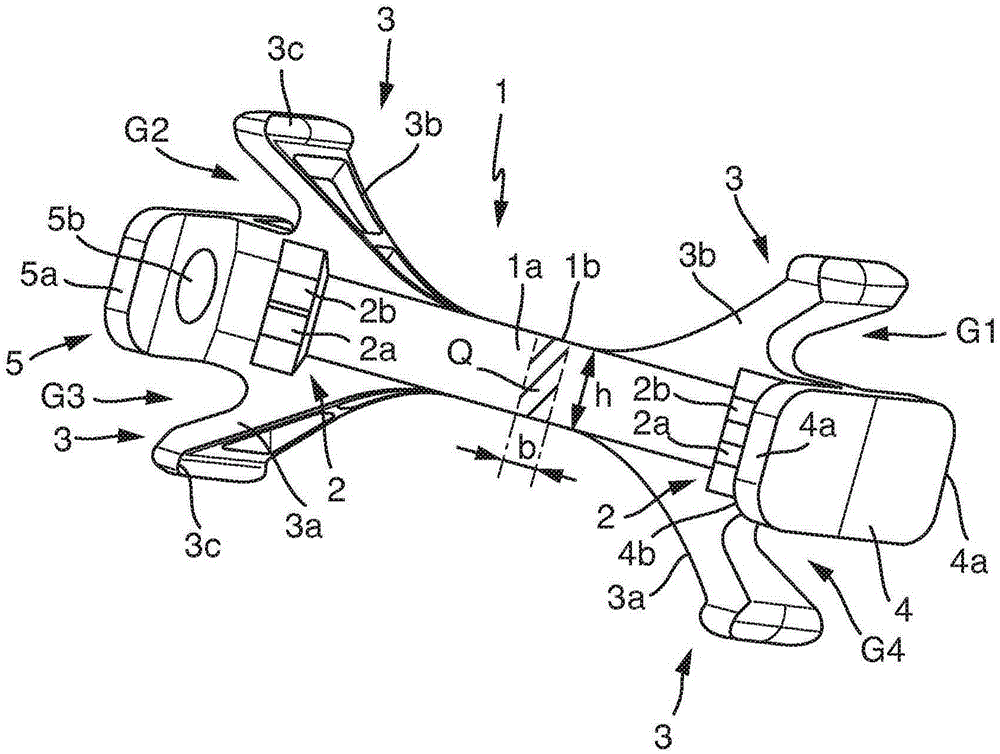
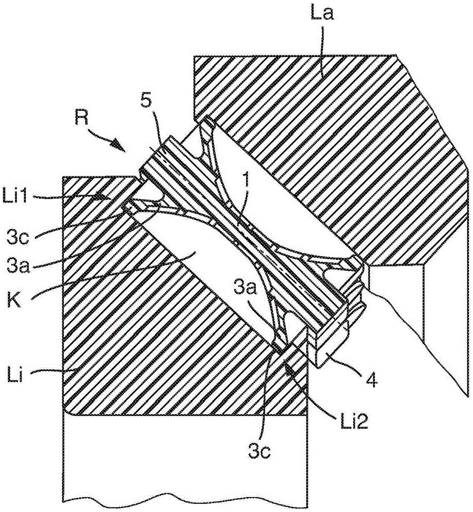
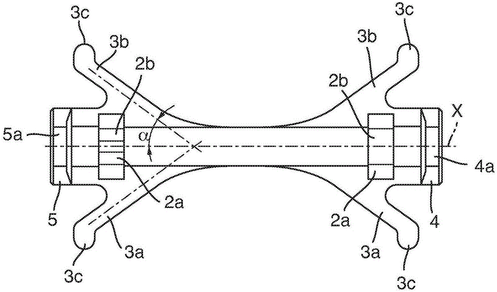
[0031] according to figure 1 The illustration of shows a rolling element guide element according to the invention for a large rolling bearing embodied as a tapered roller bearing. The rolling element guide element comprises an inner beam 1 which, in the installed state, is arranged between two adjacent rolling elements and forms a second One and second beam wall 1a, 1b. Furthermore, the rolling body guide element also comprises a thrust structure 2 configured in the region of the respective beam wall 1a, 1b to provide at least one roller thrust area 2a, 2b supporting the respective rolling body in the direction of revolution.

[0032] The radial and axial guidance of the rolling element guide element takes place via a guide mechanism which is formed exclusively integrally from the rolling element guide element. Thus, the rolling body guide element comprises a special radial guide structure 3 for radially guiding the inner beam 1 and first and second side edge pieces 4, 5 whi...


PUM


Abstract

The invention relates to a rolling body guide element for a roller bearing, having an inner web (1) that is arranged between two adjacent rolling bodies in the installed state and forms a first and second web wall (1a, 1b) facing a respective rolling body at the radial level of the rolling body axes, a run-up structure (2) formed in the region of the respective web wall to provide at least one roller run-up zone supporting the respective rolling body in the circumferential direction, and a radial guide structure (3) for radially guiding the inner web. According to the invention, the rolling body guide element comprises first and second lateral edge pieces (4, 5) which, on sides of the rolling body guide element facing away from one another, rise up above the end faces of the adjacent rolling body and reach over said end faces.

Description

technical field [0001] The invention relates to a rolling element guide, in particular for large rolling bearings of the tapered roller type carrying axial and radial loads, wherein such a rolling element guide is arranged in each case between two successive rolling elements of the rolling bearing In this case, two adjacent rolling elements are supported relative to each other in the circumferential direction, and a minimum distance is ensured between these rolling elements, thereby avoiding direct contact of the rolling elements. Background technique [0002] Hitherto, for large tapered roller bearings (diameter > 2000 mm) in the wind power sector and other fields of application of this bearing size, rolling-element guiding cages were generally used, which can be implemented, for example, as so-called pin-type cage or plastic segmented cage. Plastic segmented cages place a requirement on the bearing design that they must have a multiple of the number of rollers that are...

Claims


Application Information

Patent Timeline
IPC IPC(8): F16C33/51F16C33/46
CPCF16C33/374F16C19/386F16C33/3706F16C33/4605F16C2300/14F16C2360/31F16C19/364
Inventor 洛伦茨·贝尔约翰内斯·莫纽斯罗兰·艾希勒曼弗雷德·扬森弗洛里安·福格尔格桑扎比内·普利施基曼纽尔·雷廷格克里斯蒂安·佐伊贝特赫尔曼·盖尔克里斯托夫·梅德尔
Owner SCHAEFFLER TECH AG & CO KG
Learn More