Filling type pollen feeder

A filling and powdering device technology, which is applied in the field of bee breeding, can solve the problems of bee waste, bee colony lack of powder, time-consuming and labor-intensive problems, and achieve the effect of simple and convenient operation, large capacity and improved feeding efficiency

Inactive Publication Date: 2015-12-16
徐建怀
View PDF6 Cites 3 Cited by
  • Summary
  • Abstract
  • Description
  • Claims
  • Application Information

AI Technical Summary

Problems solved by technology

[0003] 1. The production is troublesome, time-consuming and labor-intensive, and requires certain skills;
[0004] 2. Once the production is not good or the operation is wrong or the bee colony is too weak, the bees will not accept it, which will cause a lot of waste and seriously affect the bees;
[0005] 3. If part of the powder is eaten by bees, the mother bee will lay eggs on the spleen and store honey. At this time, adding a powder spleen will often destroy the relationship between the honeycomb and the ratio of insects and bees, which will seriously affect For numerous bees, if no powder spleen is added, it will cause a lack of powder in the bee colony, which will also affect the numerous bees
[0007] 1. If the powdered cake is fed too much and the bees cannot finish eating it within a few days, the powdered cake will break down and become moldy and hard. If the powdered cake is fed too little, it will not be able to meet the needs of the bees. Frequent feeding will also take time and labor;
[0008

Method used


Image

  • Filling type pollen feeder
  • Filling type pollen feeder
  • Filling type pollen feeder

Examples


Example Embodiment

[0044] Example 1

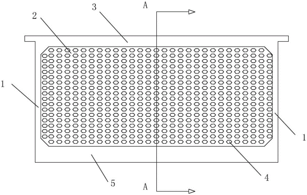
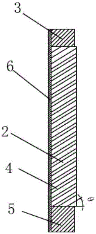
[0045] Such as Figure 1-3 As shown, the filling type powder feeder provided by the present invention is specifically explained, including a powder feeder body with an opening on the side, the powder feeder body includes a frame arranged on the bottom plate 6, and the frame includes an upper beam 3 and the side plates 1 on both sides of the lower beam 5. In this embodiment, the frame width is 27cm, the length is 45cm, and the thickness is 3cm; the width of the side plate 1 is 1.5cm, the length is 22.5cm, and the thickness is 3cm; The opening is embedded with a powder feeder 2, and the honeycomb hole 4 of the powder feeder 2 is provided with an upward inclination angle θ with the horizontal plane, and the value of the inclination angle θ is 30°-60°, preferably the inclination angle θ The value is 35°-50°, and it is more preferable that the value of the inclination angle θ is 40° or 45°. The powder feeder 2 is rectangular in which a number of honeycomb holes 4 a...

Example Embodiment

[0046] Example 2

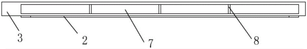
[0047] Such as Figure 4-6 As shown, this embodiment is improved on the basis of embodiment 1. The other structure is the same, the difference is: the filling type powder feeder provided by the present invention, the top surface of the powder feeder 2 is provided on the lower side of the upper beam 3. There is a downward arc structure 13, the distance from the bottom edge of the arc structure 13 to the upper beam 3 is 3-10cm, in this embodiment it is 6cm or 7.6cm, and the upper beam 3 is provided with syrup with an upward opening The upper beam 3 is provided with a syrup pool with upward openings, including a first syrup pool 7 and a second syrup pool 9 which are arranged symmetrically at the center of the upper beam 3 and separated by a partition 8. The first syrup pool 7 The shape of the bottom surface of the second syrup pool 9 and the shape of the arc structure 13 are arranged corresponding to each other.

Example Embodiment

[0048] Example 3

[0049] Such as Figure 7 As shown, this embodiment has been improved on the basis of embodiment 1. The other structures are the same. The difference is that the powder feeder 2 includes a plurality of transverse partitions 10 and vertical partitions 11 intersecting in the opening. A number of honeycomb holes 4 arranged in sequence are formed between the transverse partition 10 and the longitudinal partition 11, and the honeycomb holes 4 have a length of 0.5 to 2.0 cm, preferably 1.5 cm, and a width of 0.5 to 1.5 cm, preferably 1.0 cm. The honeycomb hole 4 is provided with an upward inclination angle θ with the horizontal plane, and the inclination angle θ is 30°-60°. Preferably, the inclination angle θ is 35°-50°, and preferably, the inclination angle θ is 40° or 45°.

[0050] The specific use method of the filling powder feeder provided by the present invention is as follows:

[0051] 1. After mixing pollen or substitutes with water, sugar or honey, use a wooden...


PUM

PropertyMeasurementUnit
Lengthaaaaaaaaaa
Widthaaaaaaaaaa
Inclinationaaaaaaaaaa

Abstract

The invention relates to the technical field of bee breeding, in particular to a filling type pollen feeder. The filling type pollen feeder comprises a pollen feeder body with one side face provided with an opening. The pollen feeder comprises a frame arranged on a bottom plate. The frame comprises side plates arranged on the two sides of an upper beam and the two sides of a lower beam. The pollen feeder body is embedded into the opening. An upward inclined angle theta is formed between honeycomb holes of the pollen feeder body and the horizontal plane and ranges from 30 degrees to 60 degrees. A downward arc structure is formed at the position, on the lower side of the upper beam, of the top face of the pollen feeder body. The upper beam is provided with syrup pools with upward openings, namely a first syrup pool and a second syrup pool, and the bottom surface shape of the first syrup pool and the bottom surface shape of the second syrup pool correspond to the shape of the arc structure. According to the filling type pollen feeder, when much powder paste or viburnum plicatum is fed, the bees cannot eat up the powder paste or viburnum plicatum in a few days, and the powder paste or viburnum plicatum cannot go bad; when the low-temperature overcast and rainy weather occurs continuously, the swarm cannot lack pollen, time and labor are saved in the feeding process, efficiency can be improved, operation is simple and convenient when the swarm is inspected, and the inspection effect is ideal.

Description

technical field [0001] The invention relates to the technical field of bee breeding, in particular to a filling powder feeder. Background technique [0002] In the prior art, the traditional powder feeding method 1 is adopted: the dried pollen is sprayed with water and melted, and then mixed with about 10% dry white sugar, sieved into the appearance of natural fresh flower powder, then poured into the honeycomb, and then sprayed with dilute powder. The honey water is placed in the bee colony, and the bees eat it after processing. This kind of feeding powder has the following disadvantages: [0003] 1. The production is troublesome, time-consuming and labor-intensive, and requires certain skills; [0004] 2. Once the production is not good or the operation is wrong or the bee colony is too weak, the bees will not accept it, which will cause a lot of waste and seriously affect the bees; [0005] 3. If part of the powder is eaten by bees, the mother bee will lay eggs on the s...

Claims


Application Information

Patent Timeline
IPC IPC(8): A01K53/00
CPCA01K53/00
Inventor 徐建怀
Owner 徐建怀
Why Eureka
Try Eureka