Water bladder irrigation drainage tube

A drainage tube and nasal gallbladder technology, which is applied in the field of water bag nasal gallbladder irrigation and drainage tube, can solve the problems of drainage tube prolapse, small fixation force, and slow bile flow rate, and achieve easy discharge, increase fixation force, and reduce bile duct pressure Effect

Active Publication Date: 2019-01-01
DALIAN UNIV
View PDF9 Cites 1 Cited by
  • Summary
  • Abstract
  • Description
  • Claims
  • Application Information

AI Technical Summary

Problems solved by technology

[0003] At present, the nasal and biliary drainage tubes in clinical use are all single-channel drainage tubes. The body of the tube is straight, and the head end is bent into a loop. Under the action, bile can be drawn out through the lumen, but the flow rate of bile is slow, and viscous purulent bile is not easy to discharge, and its circular side hole is small, and debris can easily block the side hole of the drainage tube
This drainage tube has the following deficiencies: 1. In order to keep the drainage tube unobstructed and promote the discharge of viscous purulent bile, it is necessary to repeatedly use physiological saline to rinse the nasobiliary duct after the operation, so as to keep the drainage tube unobstructed and dilute the intrahepatic bile , promote the discharge of viscous purulent bile and gravel, and increase the clinical workload; 2. Since the drainage tube is straight, when the bile is sucked, the bile duct wall mucosa is easily adsorbed to the side hole of the drainage tube, resulting in backwashing of the flushing fluid Difficult; 3. The head of the drainage tube is naturally looped, and its fixation force is small, and the drainage tube is prone to prolapse; 4. During the extubation process, the head of the loop drainage tube can cause damage to the bile duct and intestinal mucosa, and even induce Acute cholangitis, acute pancreatitis, upper gastrointestinal bleeding and other complications

Method used


Image

  • Water bladder irrigation drainage tube
  • Water bladder irrigation drainage tube
  • Water bladder irrigation drainage tube

Examples


Embodiment Construction

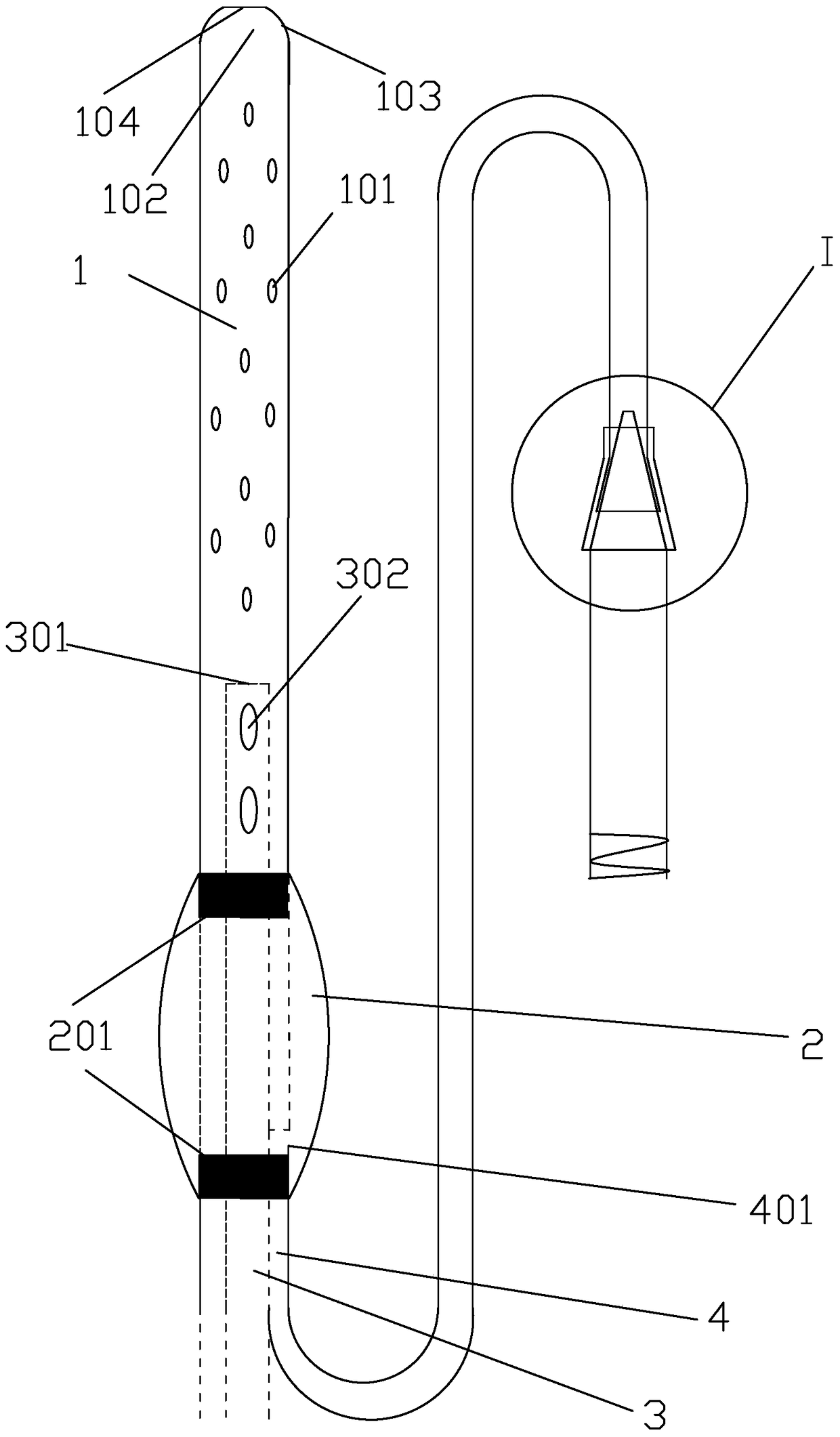
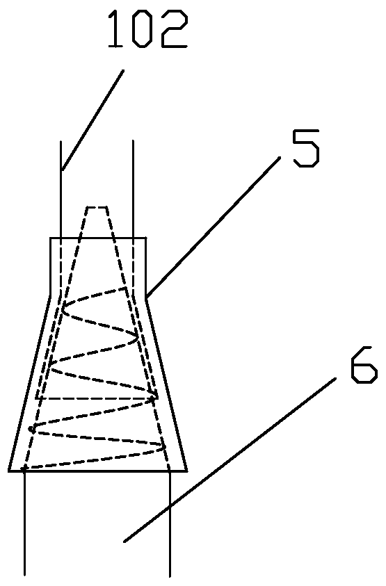
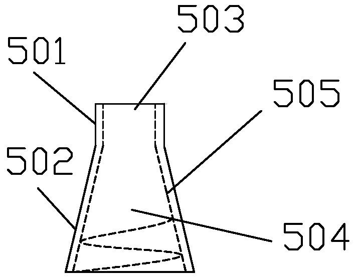
[0034] Such as Figure 1-Figure 10 As shown, a water bag type nasobiliary irrigation and drainage tube includes a main pipe 1, a pipe I3 ​​with a closed end 301 located in the main pipe 1 and a balloon membrane 2 sleeved on the outer wall of the main pipe 1. The cross section of the capsule membrane 2 is quincunx-shaped, and the main pipe 1 is also provided with a pipeline II4 communicating with the balloon membrane 2, and the other end of the pipeline II4 is connected to the tube 6 through the cap 5, and the tube 6 The other end is connected with the three-way valve, and the cap 5 has a cylindrical head 501 and a truncated conical tail 502, the small end of the truncated conical tail 502 is fixedly connected with the cylindrical head 501, and the cylindrical head 501 is provided with a through hole I503 matching the outer diameter of the pipe II4, the pipe 6 has a frustum-shaped head 601, the outer surface of the frustum-shaped head 601 is provided with external threads, and ...


PUM


Abstract

The invention discloses a water-bag type nose-bile flushing drainage tube. The drainage tube comprises a main tube, a pipeline I and a balloon film, the pipeline I is located inside the main tube and provided with a closed end, and the outer wall of the main tube is sleeved with the balloon film. The cross section of the balloon film is in a plum blossom shape, a pipeline II communicated with the balloon film is further arranged inside the main tube, multiple lateral holes I and multiple lateral holes II are formed in the main tube and located in the pipe section part, above the balloon film, of the main tube, and the lateral holes II and the pipeline I are communicated. Automatic flushing is achieved, the oval lateral holes are adopted for reducing the probability of blockage, the flowing direction of flushing fluid in the bile duct is uniform with the discharging direction of bile, and it can be avoided that the flushing fluid and the bile reversely flow. The balloon film capable of being expanded and filled is arranged, in this way, the fixing force of the drainage tube is increased, an anti-slipping effect is achieved, and damage to the bile duct, intestinal canal and pharynx and larynx mucosae will not be caused in the process of taking out the drainage tube.

Description

technical field [0001] The invention relates to a flushing and drainage tube, in particular to a water bag type nasal gallbladder flushing and drainage tube. Background technique [0002] With the continuous development of endoscopic technology and the continuous improvement of its accessories, duodenoscopy (ERCP) has become an important measure for the treatment of hepatobiliary and pancreatic diseases, including common bile duct stones, acute obstructive suppurative cholangitis, bile duct injury , biliary stricture, biliary complications after liver transplantation, etc. Compared with traditional laparotomy, this technique has the advantages of less trauma, high safety factor, and faster recovery. After ERCP treatment, external nasobiliary drainage tubes are routinely placed to drain infectious bile, bile sludge, and gravel, which can reduce the incidence of postoperative cholangitis and the recurrence rate of choledocholithiasis. [0003] At present, the nasal and bilia...

Claims


Application Information

Patent Timeline
Patent Type & Authority Patents(China)
IPC IPC(8): A61M25/10A61M3/02
Inventor 张诚杨玉龙马跃峰
Owner DALIAN UNIV
Why Eureka
Try Eureka