Multi-station continuous workpiece stamping device

A punching device and multi-station technology, which is applied to positioning devices, feeding devices, storage devices, etc., can solve problems such as low production efficiency, and achieve the effects of simple structure, low cost and convenient use.

Inactive Publication Date: 2015-12-16
苏州金鸿顺汽车部件股份有限公司
View PDF5 Cites 11 Cited by
  • Summary
  • Abstract
  • Description
  • Claims
  • Application Information

AI Technical Summary

Problems solved by technology

For parts that need to change the positioning direction during the stamping process, due to the limitation of the internal space of the mold and the ability of the manipulator, the parts can only be produced by manual operation, and the production efficiency is low

Method used


Image

  • Multi-station continuous workpiece stamping device
  • Multi-station continuous workpiece stamping device
  • Multi-station continuous workpiece stamping device

Examples


Embodiment Construction

[0018] The specific embodiments of the present invention will be described in detail below with reference to the accompanying drawings.

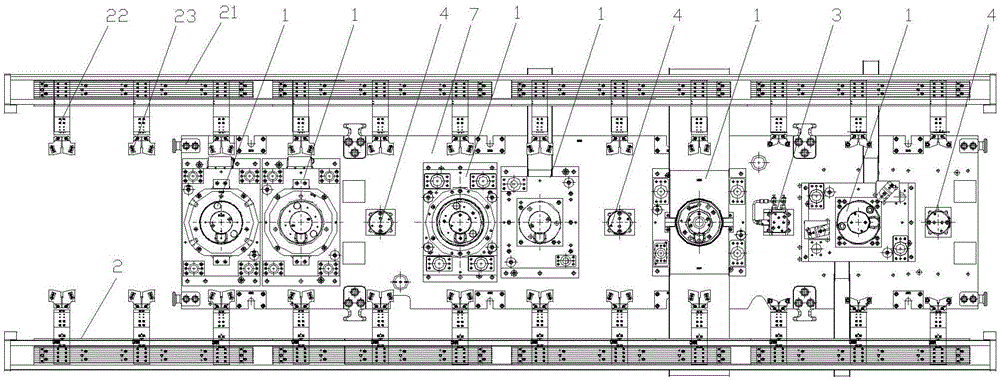
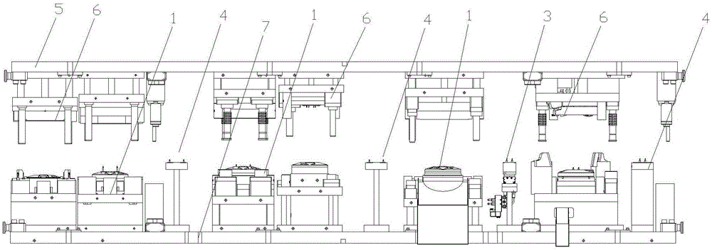
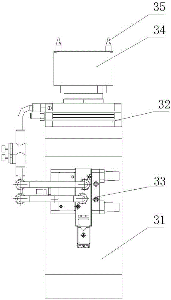
[0019] Such as Figure 1-4 As shown, a multi-station continuous stamping device for a workpiece includes a plurality of lower stamping dies 1 arranged on a machine table 7 in the order of stamping and a plurality of upper stamping dies 6 arranged on an upper stamping seat 5. The machine 7 is provided with a clamping device 2 for conveying the workpiece to the next station. The machine 7 is equipped with an angle adjustable rotating device 3 between the two punching stations where the workpiece needs to be turned, and any lower punching die The distance between 1 and the adjacent rotating device 3 or lower punching die 1 is equal. The rotating device 3 includes a fixed seat 31 installed on the machine table 7. The upper surface of the fixed seat 31 is provided with a rotating cylinder 32 with an adjustable rotation angle. The fixed seat 31 is p...


PUM


Abstract

The invention discloses a multi-station continuous workpiece stamping device. The device comprises a plurality of lower stamping dies arranged on a machine table according to a stamping sequence and a plurality of upper stamping dies arranged on an upper stamping base. A clamping conveying device for conveying a workpiece to the next station is arranged on the machine table. A rotating device is arranged at the portion, between two stamping stations where workpiece needs to be steered, of the machine table. The distance between any lower stamping die and the adjacent rotating device or a lower stamping die is equal. The rotating device comprises a fixed base installed on the machine table. A rotating air cylinder is arranged on the upper surface of the fixed base. A starting electromagnetic valve controlling the rotating air cylinder to act is arranged on the fixed base. A workpiece positioning block is connected to a rotating base of the rotating air cylinder. Two positioning pins matched with the workpiece to be machined are arranged on the workpiece positioning block. The multi-station continuous workpiece stamping device can be used for horizontally rotating the workpiece by a certain angle in the machining process.

Description

Technical field [0001] The invention relates to a multi-station continuous punching device for workpieces. Background technique [0002] The current multi-station stamping can only meet the stamping production of parts in the same direction before and after the process parts. For the parts that need to change the positioning direction during the stamping process, due to the limitation of the internal space of the mold and the capacity of the manipulator, the parts can only be produced by manual operation, and the production efficiency is low. Summary of the invention [0003] The technical problem to be solved by the present invention is to provide a multi-station continuous punching device which can rotate the angle of the workpiece horizontally during the processing. [0004] In order to solve the above-mentioned technical problems, the technical solution adopted by the present invention is: a multi-station continuous punching device for workpieces, including a plurality of lower...

Claims


Application Information

Patent Timeline
IPC IPC(8): B21D43/10
Inventor 申利军
Owner 苏州金鸿顺汽车部件股份有限公司
Why Eureka
Try Eureka