Belt wheel structure for robot

A robot and pulley technology, applied in the field of manipulators, can solve the problems that the belt tension is not easy to be too tight, does not use pulleys for transmission, and affects the life of the belt, and achieves the effect of compact installation structure, wide applicability, and guaranteed service life.

Active Publication Date: 2015-12-16
ZHEJIANG QIANJIANG MOTORCYCLE +1
View PDF12 Cites 9 Cited by
  • Summary
  • Abstract
  • Description
  • Claims
  • Application Information

AI Technical Summary

Problems solved by technology

But as mentioned above, this tensioning method is limited to the coaxial structure of the motor and the pulley. When the two pulleys have transmission structure input and output on both sides, the position of the pulley on the structure is fixed, so it cannot Tensioning by mounting position adjustment
[0004] The other is to increase the tension of the roller, and press a freely rotating roller on the outside of the belt to tension. Under this structure, the outer ring of the roller and the outer ring of the belt are transmitted through friction, and the movement of the robot is to move back and forth repeatedly. , and the belt tension is not easy to be too tight, too tight will affect the life of the belt and is easy to break, so the friction that can be transmitted is limited, and the roller will always slip slightly when it is transmitted by friction, causing the belt to wear
Due to the above reasons, this structure is rarely used in robots, but the engine has a similar structure. When the motor is not directly connected to the robot, the pulley transmission structure is generally not used.

Method used


Image

  • Belt wheel structure for robot
  • Belt wheel structure for robot
  • Belt wheel structure for robot

Examples


Embodiment Construction

[0020] The following are specific embodiments of the present invention and in conjunction with the accompanying drawings, the technical solutions of the present invention are further described, but the present invention is not limited to these embodiments.

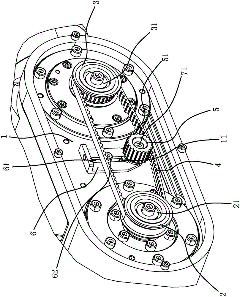
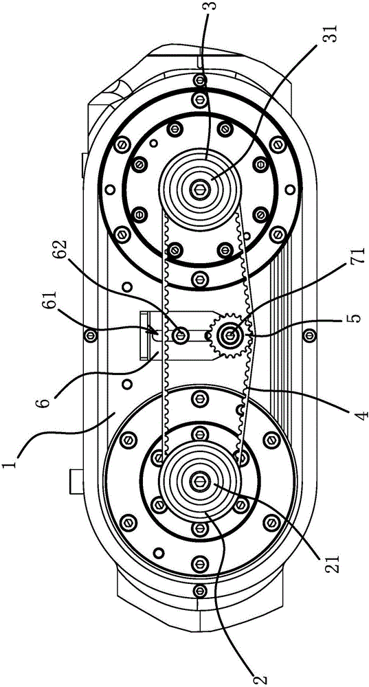
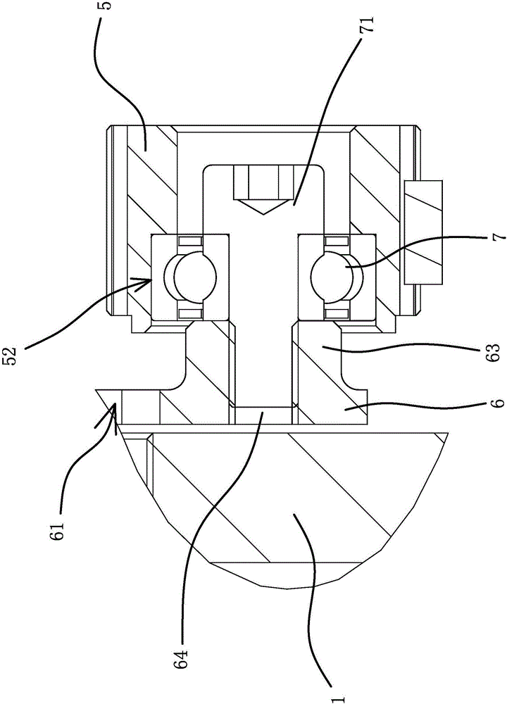
[0021] This example Figure 1 to Figure 3 As shown, the robot includes a joint 1 connecting the mechanical arm, and the pulley structure of the robot includes a driving pulley 2 connected to a drive shaft 21, a driven pulley 3 connected to a driven shaft 31, and a drive pulley 2 and a driven pulley 3 connected to each other. The toothed belt 4 between the driven pulleys, the driving pulley 2 and the driven pulley 3 are all arranged in the joint 1 and the distance between the driving pulley 2 and the driven pulley 3 is fixed, and the driving pulley is located in the joint 1 2 and the driven pulley 3 are also provided with an auxiliary pulley 5 with gear teeth 51, the auxiliary pulley 5 is located on the inner side of the to...


PUM


Abstract

The invention provides a belt wheel structure for a robot, belonging to the technical field of mechanical arms. The technical problems that a current belt wheel structure for the robot is not suitable for the robot and the like are solved. The robot comprises a joint for being connected with a mechanical arm; the belt wheel structure for the robot comprises a driving belt wheel connected with a driving rotation shaft, a driven belt wheel connected with a driven rotation shaft and a tooth-form belt arranged between the driving belt wheel and the driven belt wheel; the driving belt wheel and the driven belt wheel are both arranged in the joint, and the distance between the driving belt wheel and the driven belt wheel is constant; an auxiliary belt wheel with wheel teeth is also arranged between the driving belt wheel and the driven belt wheel in the joint; the auxiliary belt wheel is located on the inner side of the tooth-form belt; and the auxiliary belt wheel can be meshed with one side of the tooth-form belt and enable the tooth-form belt to keep tensioned. The belt wheel structure for the robot disclosed by the invention has the advantages that the tooth-form belt can be enabled to maintain proper tensity, and the stability of transmission is improved.

Description

technical field [0001] The invention belongs to the technical field of manipulators and relates to a pulley structure for a robot. Background technique [0002] With the development of industrial automation, the application of industrial robots is becoming more and more common. With the complexity of the use environment, the degree of freedom of the robotic arm of the robot is getting higher and higher. At present, the general mechanical arm has six degrees of freedom. The degree of freedom is controlled by the motor or motor. With the increase of the degree of freedom of the mechanical arm, the wrist at the end is generally the executive segment, and its joint structure needs to be relatively small to complete the processing, so it is difficult to reduce the motor or motor directly to the joint. At present, the control of the end mechanical arm is realized by means of belt transmission. [0003] Belt transmission needs to consider the tension of the belt. At present, there...

Claims


Application Information

Patent Timeline
Patent Type & Authority Applications(China)
IPC IPC(8): B25J17/00
CPCB25J17/00
Inventor 江加凯邓定红孔民秀陶胜美
Owner ZHEJIANG QIANJIANG MOTORCYCLE
Why Eureka
Try Eureka