


Quick Research
Generate reliable direction feasibility study reports for your R&D in just a few steps.

Technical Q&A
Discover and master advanced knowledge NOW. Basics, ideas, possibilities, all at once.

Find Solutions
As an expert in R&D theories, this can generate solutions to your technical problems instantly.

Evaluate Feasibility
Analyze your overall solution with one click, know your potential R&D risks in advance.

Monitor Landscape
Get weekly tech updates, stay abreast of the latest tech innovations and key insights.
Hydrodynamic UAV Replenishment Device
A technology of unmanned aerial vehicles and hydrodynamics, applied in the direction of power plant types, etc., can solve the problems of being easily affected by environmental factors, high supply costs, long preparation time, etc., achieving flexible quantity and layout, small environmental factors, and suitable supply Effect
- Summary
- Abstract
- Description
- Claims
- Application Information
AI Technical Summary
Problems solved by technology
Method used
Image

Examples
Embodiment 1
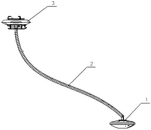
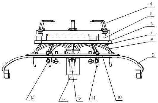
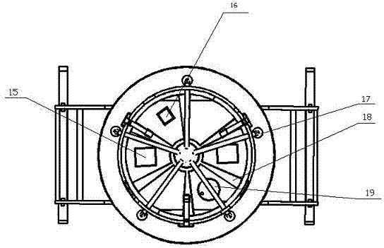
[0035] Such as Figure 1-6 shown.
[0036] A water-based UAV supply equipment, which includes:
[0037] A water surface power cabin 1, this water surface power cabin 1 provides the power required for flight as a power part of the whole equipment, and the seawater is extracted by the engine 24 installed in the water surface power cabin 1 to provide flight power; the water surface power cabin 1 also A water inlet 25, an outlet pipe 20, an auxiliary water jet 27, a seawater filtering device 28 and a propulsion device are provided. Described propulsion device is made up of two sets of identical front and back symmetrical parts, and every set of propulsion device comprises solenoid valve 21, steering mechanism 23, vector nozzle 22 and auxiliary water spray port 27, and the water inlet of vector nozzle 22 and invention machine 24 The water outlets are connected, the vector nozzles 22 are symmetrically distributed on the water surface power cabin, the solenoid valve 21 is installed...
Embodiment 2
[0043] The difference from Embodiment 1 is that four ultrasonic rangefinders are installed at the front, rear, left, and right sides of the airframe to assist the airframe to fly autonomously in severe weather conditions and complex environments.
Embodiment 3
[0045] The difference from Embodiment 1 is that the number of vector nozzles in the water surface power cabin is 1-3, and a symmetrically distributed layout is adopted; the number of nozzles in the body is 3-11, and the corresponding number and connection Both have the same number of solenoid valves, and different numbers of nozzles correspond to different layouts.
[0046] The working principle of the present invention is:
[0047] When the present invention works, the seawater is extracted by the engine 24 in the water surface power cabin 1, and the high-speed seawater reaches the water inlet pipe 13 of the body 3 after passing through the connecting hose 2, and then passes through the reversing shunt pipe 8 to convert the upward high-speed seawater Become 5 downward currents, by controlling the solenoid valve 17 installed on the outside of the chassis 10, the water spray volume and the water spray speed of each water spray pipeline can be adjusted.
[0048] Two vector nozz...
PUM
 Abstract
Description
Claims
Application Information
 - R&D Engineer
- R&D Manager
- IP Professional
- Industry Leading Data Capabilities
- Powerful AI technology
- Patent DNA Extraction
Browse by: Latest US Patents, China's latest patents, Technical Efficacy Thesaurus, Application Domain, Technology Topic, Popular Technical Reports.
© 2024 PatSnap. All rights reserved.Legal|Privacy policy|Modern Slavery Act Transparency Statement|Sitemap|About US| Contact US: help@patsnap.com