Optical vacuum coating process

A vacuum coating and process technology, applied in vacuum evaporation coating, metal material coating process, sputtering coating and other directions, can solve the problem of low working efficiency of optical fiber tip cleaning, affecting the quality of optical fiber line communication, and poor optical fiber positioning. It can improve the cleaning efficiency and cleaning quality, solve the problem of easy pinching and breakage of optical fibers, and solve the effects of unstable positioning.

Inactive Publication Date: 2015-12-16
SINY OPTIC COM CO
View PDF5 Cites 6 Cited by
  • Summary
  • Abstract
  • Description
  • Claims
  • Application Information

AI Technical Summary

Problems solved by technology

[0002] With the rapid development of optical fiber communication technology, the use of optical fiber lines and various optical fiber conversion equipment is very large. Since optical fiber equipment mainly realizes data transmission through optical path reflection, the reflective ability at the end of the optical fiber interface directly affects the optical fiber line. Communication quality. In order to solve this problem, the current common practice is to coat the fiber end. However, in the current optical fiber coating process, the optical fiber is often positioned with a large fixture, and then the fiber end is manually polished. Carry out cleaning treatment so that the cleanliness of the optical fiber end meets the coating requirements. In actual operation, it is found that this processing technology of the optical fiber end often results in unstable positioning of the optical fiber or the phenomenon that the optical fiber is clamped by the clamp. At the same time, the optical fiber end is cleaned. The working efficiency of the operation is also very low, and it is difficult to effectively meet the actual needs of the use of optical fibers. Therefore, in view of this situation, it is urgent to develop a new optical fiber coating process to meet the needs of actual use.

Method used


Image

  • Optical vacuum coating process

Examples


Embodiment 1

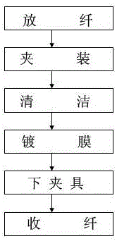
[0019] like figure 1 As shown, an optical vacuum coating process includes the following steps:

[0020] Step 1: Unwind the fiber, pull out the fiber head to be processed from the coiled fiber optic disk, keep the pulled fiber straight, and the fiber length is 10 cm;

[0021] Step 2: Clamping, embedding the released fiber head to be processed in the positioning fixture, and adjusting the clamping force of the fixture and positioning the fiber through the positioning adjustment bolt, and at least 35 fiber heads are evenly distributed on the fixture; The third step: cleaning. After the optical fiber head and the fixture are installed and positioned, the fiber head and the fixture are placed in the circulating ultrapure water for cleaning, and the cleaning solution and the fiber head are ultrasonically driven at the same time. The cleaning time is 3 minutes, and the temperature of the cleaning solution is constant at 42°C during the cleaning process;

[0022] After the cleaning ...

Embodiment 2

[0027] like figure 1 As shown, an optical vacuum coating process includes the following steps:

[0028] Step 1: Unwind the fiber, pull out the fiber head to be processed from the coiled fiber optic disk, keep the pulled fiber straight, and the fiber length is 15 cm;

[0029] Step 2: Clamping, embedding the released fiber head to be processed in the positioning fixture, and adjusting the clamping force of the fixture and positioning the fiber through the positioning adjustment bolt, and at least 35 fiber heads are evenly distributed on the fixture;

[0030] The third step: cleaning. After the optical fiber head and the fixture are installed and positioned, the fiber head and the fixture are placed in the circulating ultrapure water for cleaning, and the cleaning solution and the fiber head are ultrasonically driven at the same time. The cleaning time is 5 minutes, and the temperature of the cleaning solution is constant at 45°C during the cleaning process;

[0031] After clea...


PUM

PropertyMeasurementUnit
Lengthaaaaaaaaaa
Lengthaaaaaaaaaa

Abstract

The invention discloses an optical vacuum coating process which comprises the following six steps: unreeling optical fiber heads, clamping the optical fiber heads, cleaning the optical fiber heads, coating the optical fiber heads, discharging the optical fiber heads from a clamp and reeling the optical fiber heads. By adopting the optical vacuum coating process disclosed by the invention, on one hand, the clamping quality and clamping efficiency of the optical fiber heads are effectively improved, and the defects that the positioning is unstable and optical fibers are easy to pinch off because lines are easy to get out by using a clamp for fixing the optical fiber heads in the prior art are effectively overcome; and on the other hand, the cleaning working efficiency and cleaning quality of the optical fiber heads are effectively improved and a good foundation is laid for improvement on optical fiber coating quality.

Description

technical field [0001] The invention relates to an optical vacuum coating process, and belongs to the technical field of optical fiber coating processing technology. Background technique [0002] With the rapid development of optical fiber communication technology, the use of optical fiber lines and various optical fiber conversion equipment is very large. Since optical fiber equipment mainly realizes data transmission through optical path reflection, the reflective ability at the end of the optical fiber interface directly affects the optical fiber line. Communication quality, in order to solve this problem, the current common practice is to coat the optical fiber end, and when the current optical fiber coating process, often use a large fixture to position the fiber, and then use manual grinding and other methods to adjust the fiber end. Carry out cleaning treatment to make the cleanliness of the optical fiber end meet the coating requirements. In actual operation, it is f...

Claims


Application Information

Patent Timeline
IPC IPC(8): C23C14/22
Inventor 李卫超李卫伟
Owner SINY OPTIC COM CO
Why Eureka
Try Eureka