
Floor-type slant-legged steel truss bracket of lower transverse beam of large-span cable tower

A large-span, floor-to-ceiling technology, applied to bridges, bridge parts, bridge construction, etc., can solve the problems of difficulty in removing temporary pile caps, save construction materials and labor costs, increase overall stability, and enhance overall The effect of stability

Inactive Publication Date: 2015-12-16
THE SECOND CONSTR OF CTCE GROUP
View PDF8 Cites 11 Cited by
  • Summary
  • Abstract
  • Description
  • Claims
  • Application Information

AI Technical Summary

Problems solved by technology

[0004]1. The construction period of the temporary buttress is long. After the lower beam is poured, uneven settlement may occur between different pile caps, which will affect the construction quality
[0005], large investment and high cost for temporary structure construction
[0006] After the completion of the construction of the lower beam, affected by the clearance of the building, it is very difficult to remove the temporary pile cap

Method used


Image

  • Floor-type slant-legged steel truss bracket of lower transverse beam of large-span cable tower
  • Floor-type slant-legged steel truss bracket of lower transverse beam of large-span cable tower
  • Floor-type slant-legged steel truss bracket of lower transverse beam of large-span cable tower

Examples


Embodiment

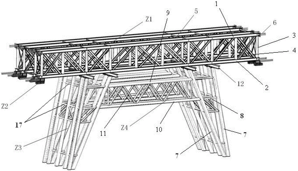
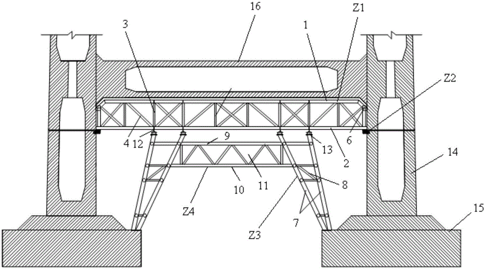
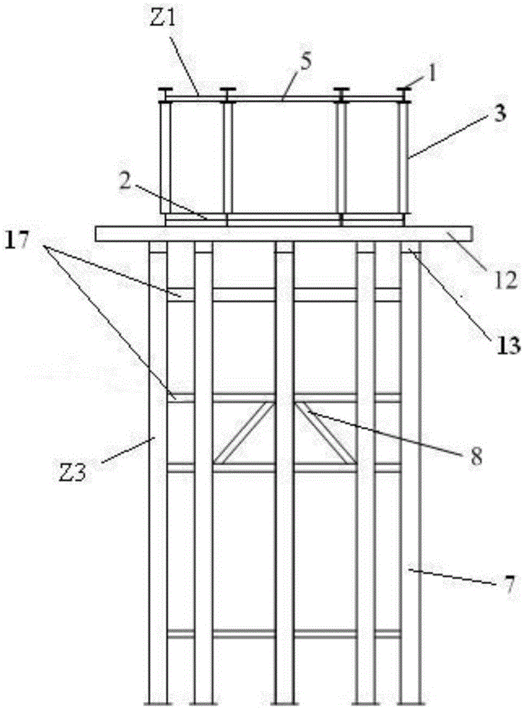
[0031] Example: Combine Figure 1~Figure 3 As shown, this large-span cable tower lower beam floor-standing inclined-leg steel truss support provided by the present invention is installed on the bottom caps 15 of tower columns 14 on both sides of the cable tower lower beam 16. Z2, oblique leg bracket Z3, anti-inclining parallel connection Z4, longitudinal distribution beam 12 and drop frame device 13 are jointly composed.

[0032] The steel truss Z1 is located below the lower beam 16 of the cable tower to bear the load of the lower beam 16 of the cable tower. The diagonal leg supports Z3 are symmetrically arranged left and right, and the bottom of each diagonal leg support Z3 is supported on the bottom of the corresponding side tower column 14. On stage 15, see for details figure 2 As shown; the top of each slant leg support Z3 is fixed with a landing gear 13, and the top of the landing gear 13 is fixed with longitudinal distribution beams 12 arranged forward and backward...


PUM


Abstract

The invention discloses a floor-type slant-legged steel truss bracket of a lower transverse beam of a large-span cable tower. The steel truss bracket is mounted on bottom bearing platforms of tower columns on two sides of the lower transverse beam of the cable tower. The steel truss bracket is characterized by comprising a steel truss, slant-legged brackets in bilateral symmetry arrangement, and an anti-introversion lateral bracing connected with the slant-legged brackets on the two sides, wherein the bottom of each slant-legged bracket is propped against the bottom bearing platform of the tower column on the corresponding side; the steel truss is supported at the tops of the slant-legged brackets. The feasible floor-type slant-legged steel truss bracket of the lower transverse beam of the large-span cable tower, provided by the invention, aims to solve the problems existing in a conventional construction technology of a lower transverse beam. The bracket directly utilizes conventional tower columns and conventional bearing platforms as a base, and omits the investment of facilities, such as temporary buttresses in the lower transverse beam span, and the bracket has the advantages of being large in bearing capacity, small in overall deformation, stable in structure, convenient to mount and demount, and sufficient in performance application of rods.

Description

technical field [0001] The invention relates to a floor-standing inclined-leg steel truss support for the lower beam of a large-span cable tower. Background technique [0002] With the continuous improvement of modern bridge construction technology, the maturity of finite element theory, and the continuous improvement of design concepts and construction equipment, in order to relieve urban traffic pressure and enhance the landscape effect of bridges, modern bridges are moving towards large-span, ultra-wide, Lightweight direction. Cable-stayed bridges and suspension bridges have been more and more used in bridge construction because of their strong spanning capacity, ultra-wide deck and beautiful architectural shapes. The lower beam, which is the main load-bearing structure of the above-mentioned bridge, presents the characteristics of width, height and weight with the continuous increase of the bridge deck size. For example, the Minpu Bridge is the first double-deck cable-...

Claims


Application Information

Patent Timeline
IPC IPC(8): E01D19/14
Inventor 徐登云赵飞刘昌箭闫明赛宋显先姜泛金张少飞
Owner THE SECOND CONSTR OF CTCE GROUP
Learn More