Fast and high precision speed-measuring method for motor

A high-precision, velocity-measuring technology, used in linear/angular velocity measurement, velocity/acceleration/impact measurement, measurement devices, etc., to achieve the effect of improving the peripheral velocity measurement time, improving real-time performance, and reducing hysteresis

Inactive Publication Date: 2009-03-25
CHANGCHUN INST OF OPTICS FINE MECHANICS & PHYSICS CHINESE ACAD OF SCI
View PDF0 Cites 16 Cited by
  • Summary
  • Abstract
  • Description
  • Claims
  • Application Information

AI Technical Summary

Problems solved by technology

There are great limitations in practical applications. For example, in high-precision flywheel attitude control, high real-time performance is required, and this method cannot meet the requirements.

Method used


Image

  • Fast and high precision speed-measuring method for motor
  • Fast and high precision speed-measuring method for motor
  • Fast and high precision speed-measuring method for motor

Examples


Embodiment 1

[0019] Adopt the method of the present invention to carry out fast high-precision speed measuring method to DC brushless motor, carry out according to the following steps:

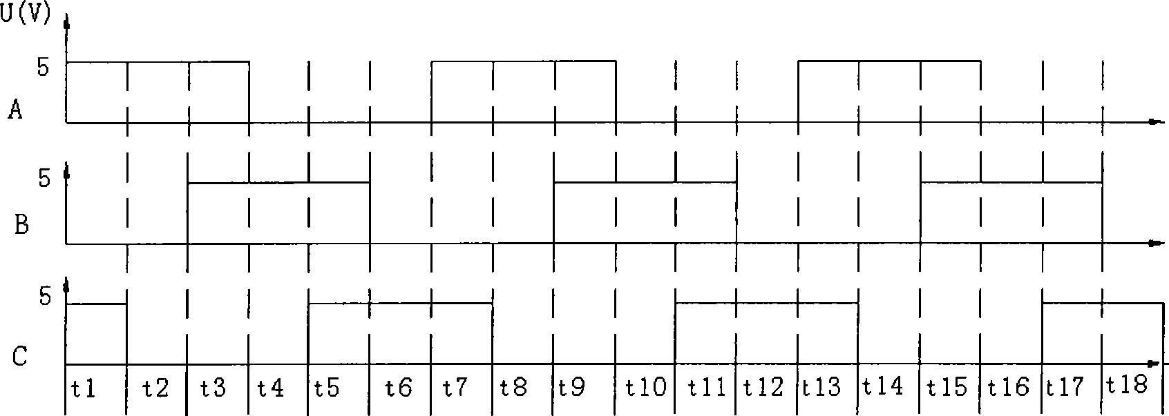
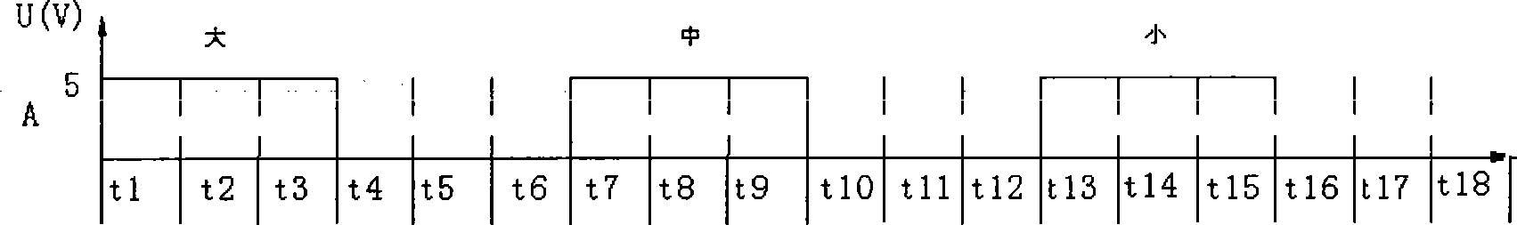
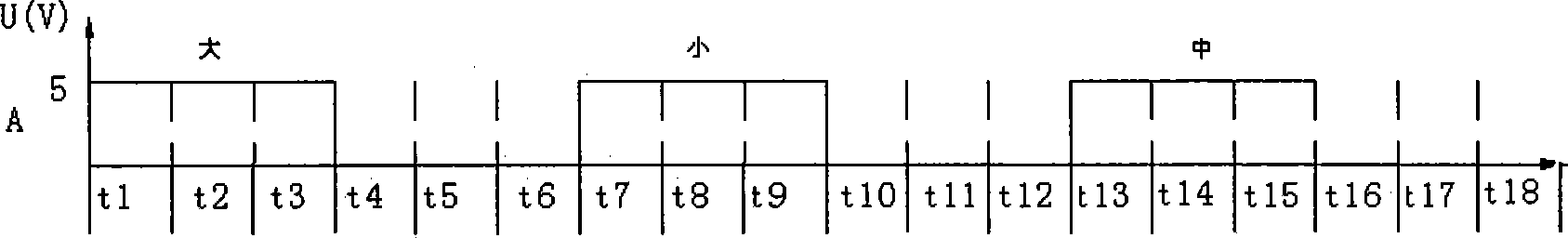
[0020] a. Calibrate the Hall signal under the drag of an external high-precision constant-speed motor, and determine the Hall signal waveforms generated by the Hall signals of A, B, and C under the action of different magnetic poles during the motor's rotation. Accurately measure the Hall signal time t1~t18 generated by the three-way Hall signal under the action of different magnetic poles, and t is the time taken for the motor to rotate one revolution. As shown figure 1 As shown, the output waveform of the Hall element is mainly produced by the installation error of the Hall element, the processing error of the stator coil and the rotor magnetic pole. The installation error of the Hall element makes the phase difference between any two Hall signals not exactly equal to 120° (three Hall 120° installation)...


PUM


Abstract

The present invention relates to a method for quickly measuring speed with high precision, in particular to a method for quickly measuring the speed of a motor with high precision. By labeling a Hall signal of the detected motor, the rotation rate of the motor which is accurately acquired by using a small section of signal in the rotation process of the motor is realized. Under the condition of stable speed, and the magnitude relation of the lengths of three Hall signals which are generated during the process of one complete revolution of the detected motor is labeled for determining the corresponding relation of a Hall element and different poles during the actual operation. Meanwhile, the trace and the positioning of the corresponding poles of the Hall signals during the operation process of the motor are completed. The primary advantage of the method is to use the small section of the signal generated during one complete revolution of the motor to accurately acquire the rotating speed of the motor speed. The quick and highly-precise speed measurement is realized.

Description

technical field [0001] The invention relates to a fast and high-precision speed measurement method, in particular to a fast and high-precision speed measurement method for a motor. Background technique [0002] In engineering practice, it is often encountered in various occasions that need to measure the speed. For example, in the test operation and control of rotating equipment such as engines, motors, hoists, and machine tool spindles, time-sharing or continuous measurement is often required, and the speed or instantaneous speed is displayed. Rotating speed. At present, there are mainly three commonly used digital speed measurement methods, namely M method (frequency method), T method (period method) and M / T method (frequency / period method). The M method is to determine the speed by measuring the number of the generated speed pulse signals within a predetermined detection time, which is suitable for high-speed measurement; the T method is to measure the time between two a...

Claims


Application Information

Patent Timeline
Patent Type & Authority Applications(China)
IPC IPC(8): G01P3/481
Inventor 白越吴一辉武俊锋
Owner CHANGCHUN INST OF OPTICS FINE MECHANICS & PHYSICS CHINESE ACAD OF SCI
Why Eureka
Try Eureka