
Relief well arrangement optimization method based on BIM technology

An optimization method and technology for depressurization wells, which are applied in excavation, infrastructure engineering, construction, etc., and can solve problems such as tediousness, zero precipitation decompression effect, and reduced depressurization and decompression efficiency of depressurization wells.

Active Publication Date: 2015-12-16
CHINA RAILWAY SHANGHAI ENGINEERING BUREAU GROUP CO LTD +1
View PDF2 Cites 0 Cited by
  • Summary
  • Abstract
  • Description
  • Claims
  • Application Information

AI Technical Summary

Problems solved by technology

[0008] The disadvantages of the arrangement method of the above-mentioned step-down wells are: when using the survey data to analyze the spatial position of the water filter pipes of the step-down wells on the geological survey drawings, it is necessary to compare multiple plans and sections, which is cumbersome and prone to drop due to human factors. The action part of the kill filter pipe is not completely or not in the confined water layer (or slightly confined water layer), resulting in a decrease in the depressurization and decompression efficiency of the depressurization well, or even zero dewatering and decompression effect

Method used


Image

  • Relief well arrangement optimization method based on BIM technology
  • Relief well arrangement optimization method based on BIM technology
  • Relief well arrangement optimization method based on BIM technology

Examples


Embodiment

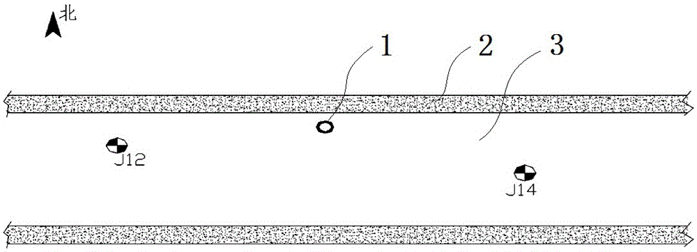
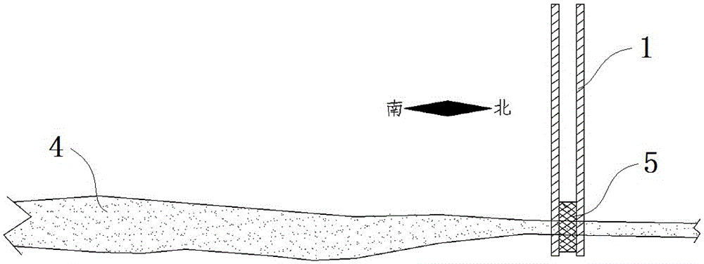
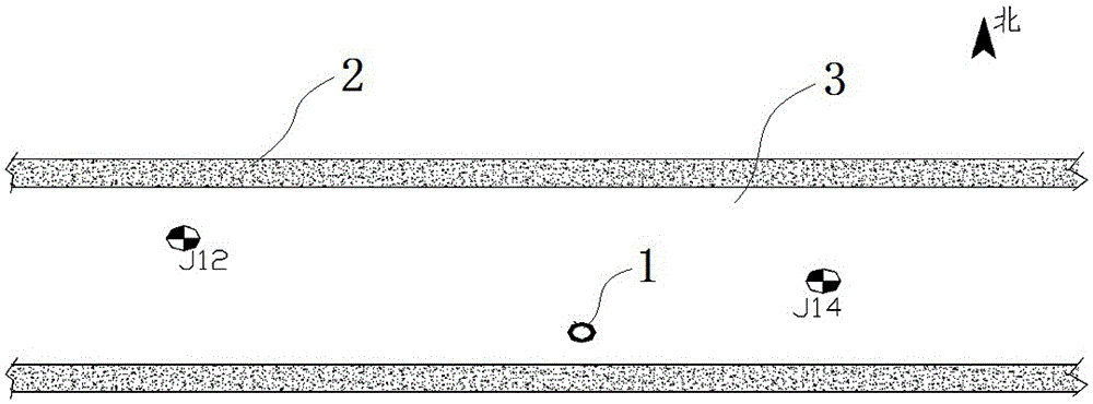
[0023] Embodiment: This embodiment specifically relates to a method for optimizing the layout of decompression wells based on BIM technology. The optimization method establishes a three-dimensional soil layer model and a decompression well model through the BIM system, and realizes that the decompression well model is spaced in the three-dimensional soil model. Visual observation and adjustment of the layout position, and by applying the three-dimensional soil layer model and the dewatering well model to carry out the simulation analysis of the water-soil mechanics numerical value, deduce the drawdown of the confined water head, and carry out comparison and screening to optimize the layout position of the depressurization well.

[0024] Such as Figure 1-4 As shown, the method for optimizing the arrangement of pressure-reducing wells in this embodiment specifically includes the following steps:

[0025] (1) Use the BIM system to linearly interpolate the distribution of soil la...


PUM


Abstract

The invention discloses a relief well arrangement optimization method based on the BIM technology, which comprises the following steps: constructing a three-dimensional soil layer model in BIM software; arranging a relief well model in the three-dimensional soil layer model according to the design position of a relief well; observing whether a water filtering pipe on the relief well acts in a target relief water layer, if not, adjusting the position of the relief well to enable the water filtering pipe on the relief well to act in the target relief water layer; constructing a three-dimensional unsteady underground water seepage numerical model; computing a water line change value in the target relief water layer after water pumping of the simulated relief well and a sedimentation change value caused by precipitation to a peripheral soil layer according to the arrangement space position and water pumping rate of the relief well; and carrying out comparison and optimization to acquire the arrangement space position of the relief well in which the drawdown in the target relief water layer meets the checking calculation requirement for resisting to sudden surging in the specification and the sedimentation change value caused by precipitation to the peripheral soil layer is minimum. The method disclosed by the invention has the advantage that the position relation between the water filtering pipe on the relief well and the target relief water layer is intuitively expressed by constructing the three-dimensional soil layer model.

Description

technical field [0001] The invention belongs to the technical field of BIM, and in particular relates to a BIM-based method for optimizing the layout of depressurization wells. Background technique [0002] With the rapid development of domestic urban rail transit and high-rise buildings, there are more and more deep foundation pit projects. In the strata with a relatively water-resistant layer above and a water-resistant layer below, the aquifer has certain pressure-bearing properties, and The foundation pit enclosure structure does not go deep into the impermeable layer, and the internal and external water systems are connected. Under this working condition, the dewatering of the foundation pit construction is particularly important. During the construction and excavation of the foundation pit, the thickness of the overlying stratum of the aquifer is reduced. When it is reduced to a certain extent, the head pressure of the confined water can burst or wash away the bottom p...

Claims


Application Information

Patent Timeline
Patent Type & Authority Applications(China)
IPC IPC(8): E02D19/10E02D17/02
Inventor 刘学明王冬冬翟昌骏周波胡洋秦钊辉杨天宇
Owner CHINA RAILWAY SHANGHAI ENGINEERING BUREAU GROUP CO LTD
Learn More