
Anti-backflow device and technology for low-potential well group incoming fluid

A low-potential, anti-backflow technology, which is applied in wellbore/well components, earthwork drilling, sealing/package, etc., can solve problems such as the inability to effectively control the backflow of incoming fluid in the well group, and reduce production management difficulties and reduce Safety and environmental protection risks, the effect of preventing fluid accumulation and freezing

Active Publication Date: 2017-09-01
PETROCHINA CO LTD
View PDF8 Cites 0 Cited by
  • Summary
  • Abstract
  • Description
  • Claims
  • Application Information

AI Technical Summary

Problems solved by technology

[0005] The purpose of the present invention is to overcome the problem in the prior art that the backflow of incoming liquid from the well group cannot be effectively controlled

Method used


Image

  • Anti-backflow device and technology for low-potential well group incoming fluid
  • Anti-backflow device and technology for low-potential well group incoming fluid
  • Anti-backflow device and technology for low-potential well group incoming fluid

Examples


Embodiment 1

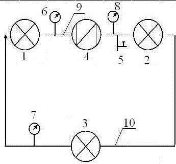
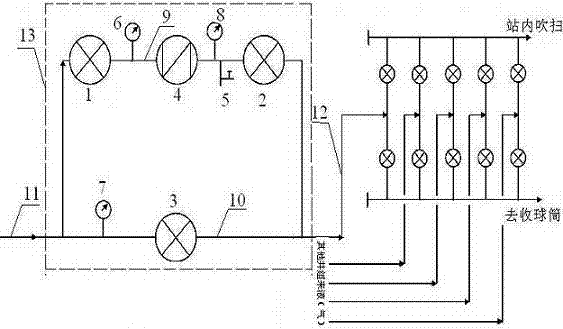
[0025] This embodiment provides a figure 1 , 2 The low-potential well group incoming liquid anti-backflow device 13 shown includes an anti-backflow pipeline 9 and a straight-through pipeline 10, the anti-backflow pipeline 9 and the straight-through pipeline 10 are connected in parallel, and one end of the parallel connection is connected to the low-potential well group incoming liquid pipeline 11 connected, and the other end is connected with the liquid inlet pipeline 12 of the main shut-in group;

[0026] The anti-backflow pipeline 9 is sequentially provided with a solenoid valve 1, a pressure gauge 6, a check valve 4, a pressure gauge 3 8, a needle valve 5, and a solenoid valve 2 according to the direction of entering the station. Station direction is provided with pressure gauge two 7, solenoid valve three 3 in turn.

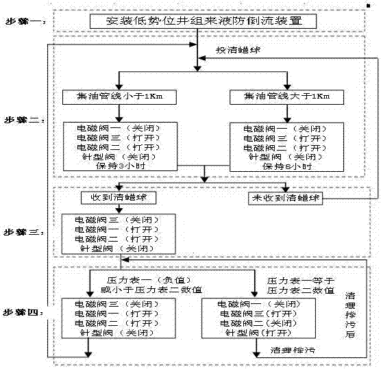
[0027] In this embodiment, the electromagnetic valve 1 mainly controls the two-way incoming liquid of the anti-backflow pipeline 9, switches the incoming l...


PUM


Abstract

The invention provides an anti-backflow device for incoming liquid in a low-potential well group, which includes an anti-backflow pipeline and a straight-through pipeline. The anti-backflow pipeline and the straight-through pipeline are connected in parallel, and one end of the parallel connection communicates with the incoming liquid pipeline of the low-potential well group. One end is connected with the liquid inlet pipeline of the main shut-in well group; the anti-backflow pipeline is provided with solenoid valve 1, pressure gauge 1, check valve, pressure gauge 3, needle valve, solenoid valve 2 in sequence according to the direction of entering the station. The pipeline is provided with pressure gauge 2 and solenoid valve 3 in sequence according to the direction of entering the station. The invention can prevent a single well from backflowing to the wellhead of a single well due to pressure relief from other well groups in the station, reduce safety and environmental protection risks, prevent oil and gas well gathering and transportation pipelines from accumulating and freezing, and reduce difficulties in production and management of oil and gas wells.

Description

technical field [0001] The invention belongs to the technical field of surface process gathering and transportation in oil and gas fields, and in particular relates to a low-potential well group anti-backflow device and a process. Background technique [0002] Oil field: At present, oil production and oil collection in various oil fields are transported from oil wells to oil gathering stations or centralized processing stations using single well pipelines. Affected by the terrain, the single well group with a lower altitude than the oil transfer station often has a high back pressure during the oil transportation process, which can reach 6MPa at the highest. The incoming oil from other well groups of the head office of the oil transfer station will flow back to the low-potential single well group through the oil gathering manifold, which will increase the load of the pumping unit and increase the time for pressure relief and venting at the wellhead. [0003] Gas field: At p...

Claims


Application Information

Patent Timeline
Patent Type & Authority Patents(China)
IPC IPC(8): E21B33/03
Inventor 宋洁曹毅谈泊于淑珍李在顺曾萍梁博羽宋劼李大昕李建阳罗晓莉侯宝东丁金岗李志伟
Owner PETROCHINA CO LTD
Learn More