U-shaped continuous deslagging equipment for vertical shaft

A U-shape, vertical shaft technology, applied in vertical shaft equipment, mining equipment, sinking, etc., can solve the problems of low slag discharge efficiency, non-continuous slag discharge, low degree of automation, etc.

Active Publication Date: 2015-12-16
CHINA RAILWAY ENGINEERING EQUIPMENT GROUP CO LTD
View PDF8 Cites 4 Cited by
  • Summary
  • Abstract
  • Description
  • Claims
  • Application Information

AI Technical Summary

Problems solved by technology

[0003] In order to solve the above technical problems, the present invention provides a U-shaped continuous slagging equipment for vertical shafts, which solves the problems of non-continuous slagging, low slagging efficiency, and low automation in vertical shafts, improves slagging efficiency, and reduces labor costs. Labor intensity

Method used


Image

  • U-shaped continuous deslagging equipment for vertical shaft
  • U-shaped continuous deslagging equipment for vertical shaft

Examples


Embodiment 1

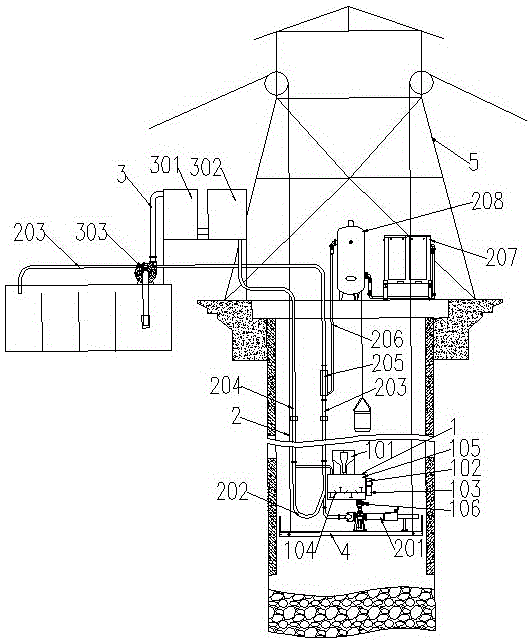
[0017] A U-shaped continuous slagging equipment for vertical shafts, such as figure 1 As shown, it includes a slag slurrying system 1 , a slag transportation system 2 , a mud separation system 3 , a bottom suspension pan 4 and a derrick 5 . Derrick 5 is fixed on the shaft upper end, and fixed pulley is fixed on the derrick 5, and bottom hanging plate 4 is suspended on upper derrick 5 by fixed pulley, and bottom hanging plate 4 is positioned at vertical shaft. The mud separation system 3 is arranged outside the shaft, and the wellhead of the shaft is provided with a sealing flat car. The slag slurrying system 1 is installed on the hanging pan 4 at the bottom of the shaft, the slurry outlet of the slag slurrying system 1 is connected to the slurry inlet of the slag transportation system 2, and the slurry outlet of the slag transportation system 2 is separated from the slurry The slurry inlet of the system 3 is connected, the slurry outlet of the slag transportation system 2 is ...

Embodiment 2

[0020] A U-shaped continuous slagging equipment for vertical shafts, such as figure 1 As shown, it includes a slag slurrying system 1 , a slag transportation system 2 , a mud separation system 3 , a bottom-hole suspension pan 4 and a derrick 5 , and the bottom-hole suspension pan 4 is suspended on the derrick 5 . The mud separation system 3 is arranged outside the vertical shaft, and the slag slurry system 1 is installed on the hanging pan 4 at the bottom of the shaft. The slurry outlet of the soil transportation system 2 is connected with the slurry inlet of the mud separation system 3, the slurry outlet of the muck transportation system 2 is connected with the muck pulping system 1, and the slurry outlet of the mud separation system 3 is connected with the muck The slurry inlet of the transport system 2 is connected.

[0021] The mud separation system 3 includes a mud separation station 301 , a mud tank 302 and a sedimentation tank 304 . The mud separation station 301, the...

Embodiment 3

[0024] A U-shaped continuous slagging equipment for vertical shafts, such as figure 1 As shown, it includes a slag slurrying system 1 , a slag transportation system 2 , a mud separation system 3 , a bottom-hole suspension pan 4 and a derrick 5 , and the bottom-hole suspension pan 4 is suspended on the derrick 5 . The mud separation system 3 is arranged outside the vertical shaft, and the slag slurry system 1 is installed on the hanging pan 4 at the bottom of the shaft. The slurry outlet of the soil transportation system 2 is connected with the slurry inlet of the mud separation system 3, the slurry outlet of the muck transportation system 2 is connected with the muck pulping system 1, and the slurry outlet of the mud separation system 3 is connected with the muck The slurry inlet of the transport system 2 is connected.

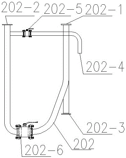
[0025] The muck transportation system 2 includes a grouting pump 201, a grout discharge pipe 203 and a grout inlet pipe 204, and the grout pump 201, the grou...


PUM


Abstract

The invention discloses U-shaped continuous deslagging equipment for a vertical shaft. The U-shaped continuous deslagging equipment comprises a residual soil slurrying system, a residual soil transportation system, a slurry separation system, a shaft bottom hanging scaffold and a headframe, wherein the shaft bottom hanging scaffold is hung on the headframe; the slurry separation system is arranged outside the vertical shaft; the residual soil slurrying system is arranged on the shaft bottom hanging scaffold; a slurry discharging hole of the residual soil slurrying system is connected with a slurry feeding hole of the residual soil transportation system; a slurry discharging hole of the residual soil transportation system is connected with a slurry feeding hole of the slurry separation system; a slurry discharging hole of the residual soil transportation system is connected with the residual soil slurrying system; and a slurry discharging hole of the slurry separation system is connected with the slurry feeding hole of the residual soil transportation system. According to the U-shaped continuous deslagging equipment, an underground slurry circulating channel is constructed by using a U-shaped pipe and other equipment through a gas lifting method, residual soil is injected to the U-shaped pipe through a grouting pump, is transported to the ground through the high-speed flowing slurry and is cleared after being separated by the slurry separation system, and the slurry is recycled. The U-shaped continuous deslagging equipment is simple in structure, automatic and continuous deslagging is realized, and the deslagging efficiency is increased.

Description

technical field [0001] The invention relates to the technical field of shaft construction equipment, in particular to a U-shaped continuous slagging equipment for shafts. Background technique [0002] In the process of excavating shafts or constructing engineering roadways, a large amount of muck or ore will be produced and need to be transported to the ground. At present, the transportation in the shaft section mainly uses hoists, buckets, etc. to lift buckets to the ground one by one. This kind of slag discharge method is intermittent slag discharge, and the transportation capacity is low, which often limits the construction progress of underground projects and increases the construction period. and cost. Contents of the invention [0003] In order to solve the above technical problems, the present invention provides a U-shaped continuous slagging equipment for vertical shafts, which solves the problems of non-continuous slagging, low slagging efficiency, and low automa...

Claims


Application Information

Patent Timeline
IPC IPC(8): E21D1/00
Inventor 肖威李建斌
Owner CHINA RAILWAY ENGINEERING EQUIPMENT GROUP CO LTD
Why Eureka
Try Eureka